ENGINE STALLS-AFTER START/AT IDLE [SKYACTIV-G]
ENGINE STALLS-AFTER START/AT IDLE [SKYACTIV-G]
SM2334606
id0103s4889200
|
Troubleshooting item |
Engine stalls-after start/at idle |
|
|---|---|---|
|
Description
|
• Stalling occurs if vehicle is left idling under no load.
• Stalling occurs when load (electric, A/C) is applied during idling.
• Stalling occurs if the accelerator pedal is depressed from an idling condition when accelerating from a stop.
|
|
|
Possible cause
|
• Engine overheating
• PCM DTC is stored
• Erratic signal to PCM
• Improper operation of A/C system
• Improper operation of drive-by-wire control system
• Purge solenoid valve malfunction
• Open circuit in MAF sensor ground circuit
• Intermittent open circuit in PCM ground circuit
• Poor fuel quality
• Air leakage from intake-air system
• Intake-air system restriction
• Electrical connector disconnected
• No battery power supply to PCM or poor ground
• Fuel leakage
• Vacuum leakage
• No signal from CKP sensor
• Erratic signal from CMP sensor
• Inadequate fuel pressure (high or low pressure side)
• Fuel injector malfunction
• Incorrect fuel injection timing
• Improper operation of electric variable valve timing control system
• Improper operation of hydraulic variable valve timing control system
• Ignition system malfunction
• Low engine compression
• Improper intake valve timing
• Improper exhaust valve timing
• Exhaust system and/or TWC restricted
• PCV valve malfunction
• Injector driver (built-into PCM) malfunction
|
|
|
Possible cause
|
|
|
 |
||
 |
||
 |
||
 |
 |
|
 |
||
 |
||
 |
||
-
Caution
-
• Verify the malfunction symptom according to not only the PID value but also the symptom troubleshooting.
Related PIDs
|
PIDs |
Reference |
|---|---|
|
APP1
|
|
|
APP2
|
|
|
ECT
|
|
|
ECT_VOLT
|
|
|
ECT2
|
|
|
ECT2_VOLT
|
|
|
FUEL_PRES
|
|
|
LOAD_CALC
|
|
|
LONG_FUEL_TRIM
|
|
|
MAF
|
|
|
MAP
|
|
|
MAP_VOLT
|
|
|
A/F_SEN_CUR
|
|
|
HO2S_OUT_VOLT
|
|
|
ENG_RPM
|
|
|
SHRT_FUEL_TRIM
|
|
|
TP_RELAT
|
|
|
VPWR
|
|
|
VSS
|
Diagnostic Procedure
|
Step |
Inspection |
Results |
Action |
|---|---|---|---|
|
1
|
VERIFY TIMING OCCURRING MALFUNCTION
• Verify the symptom.
• Does the malfunction symptom occur just after the engine is started?
|
Yes
|
Perform the symptom troubleshooting “HARD TO START/LONG CRANK/ERRATIC START/ERRATIC CRANK”.
|
|
No
|
Go to the next step.
|
||
|
2
|
VERIFY IF MALFUNCTION INCLUDES ROUGH IDLING
• Verify the symptom.
• Does the engine idle rough?
|
Yes
|
Perform the symptom troubleshooting “ENGINE RUNS ROUGH/ROLLING IDLE”.
|
|
No
|
Go to the next step.
|
||
|
3
|
VERIFY IF MALFUNCTION CAUSE IS OVERHEATING
• Access the ECT PID using the M-MDS. (See PID/DATA MONITOR INSPECTION.)
• Is the ECT PID value less than 116 °C {241 °F} during driving?
|
Yes
|
Go to the next step.
|
|
No
|
The cause of this concern could be from the cooling system overheating.
• Perform the symptom troubleshooting “COOLING SYSTEM CONCERNS-OVERHEATING”. (See COOLING SYSTEM CONCERNS-OVERHEATING [SKYACTIV-G (US)].)
|
||
|
4
|
VERIFY PCM DTC
• Perform the DTC inspection for the PCM. (See DTC INSPECTION.)
• Are any DTCs displayed?
|
Yes
|
Repair the malfunctioning location according to the applicable DTC troubleshooting.
|
|
No
|
Go to the next step.
|
||
|
5
|
VERIFY CURRENT INPUT SIGNAL STATUS
• Access the following PIDs using the M-MDS: (See PID/DATA MONITOR INSPECTION.)
• Do the PIDs indicate the correct values under the malfunction condition? (See PID/DATA MONITOR TABLE [PCM (SKYACTIV-G (US))].)
|
Yes
|
Go to the next step.
|
|
No
|
APP1, APP2 PIDs are not as specified:
• Inspect the APP sensor No.1 and No.2. (See ACCELERATOR PEDAL POSITION (APP) SENSOR INSPECTION [SKYACTIV-G (WITH CYLINDER DEACTIVATION (US))].) (See ACCELERATOR PEDAL POSITION (APP) SENSOR INSPECTION [SKYACTIV-G (WITHOUT CYLINDER DEACTIVATION (US))].)
ECT, ECT_VOLT, ECT2, ECT2_VOLT PIDs are not as specified:
• Inspect the ECT sensor No.1 and No.2. (See ENGINE COOLANT TEMPERATURE (ECT) SENSOR INSPECTION [SKYACTIV-G (WITH CYLINDER DEACTIVATION (US))].) (See ENGINE COOLANT TEMPERATURE (ECT) SENSOR INSPECTION [SKYACTIV-G (WITHOUT CYLINDER DEACTIVATION (US))].)
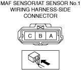
MAF PID is not as specified:
• Inspect the MAF sensor. (See MASS AIR FLOW (MAF) SENSOR INSPECTION [SKYACTIV-G (WITH CYLINDER DEACTIVATION (US))].) (See MASS AIR FLOW (MAF) SENSOR INSPECTION [SKYACTIV-G (WITHOUT CYLINDER DEACTIVATION (US))].)
MAP, MAP_VOLT PIDs are not as specified:
• Inspect the MAP sensor. (See MANIFOLD ABSOLUTE PRESSURE (MAP) SENSOR INSPECTION [SKYACTIV-G (WITH CYLINDER DEACTIVATION (US))].) (See MANIFOLD ABSOLUTE PRESSURE (MAP) SENSOR INSPECTION [SKYACTIV-G (WITHOUT CYLINDER DEACTIVATION (US))].)
A/F_SEN_CUR, SHRT_FUEL_TRIM, LONG_FUEL_TRIM PIDs are not as specified:
• Inspect the A/F sensor. (See AIR FUEL RATIO (A/F) SENSOR INSPECTION [SKYACTIV-G (WITH CYLINDER DEACTIVATION (US))].) (See AIR FUEL RATIO (A/F) SENSOR INSPECTION [SKYACTIV-G (WITHOUT CYLINDER DEACTIVATION (US))].)
HO2S_OUT_VOLT PID is not as specified:
• Inspect the HO2S. (See HEATED OXYGEN SENSOR (HO2S) INSPECTION [SKYACTIV-G (WITH CYLINDER DEACTIVATION (US))].) (See HEATED OXYGEN SENSOR (HO2S) INSPECTION [SKYACTIV-G (WITHOUT CYLINDER DEACTIVATION (US))].)
Repair or replace the malfunctioning location.
• If the malfunction remains:
|
||
|
6
|
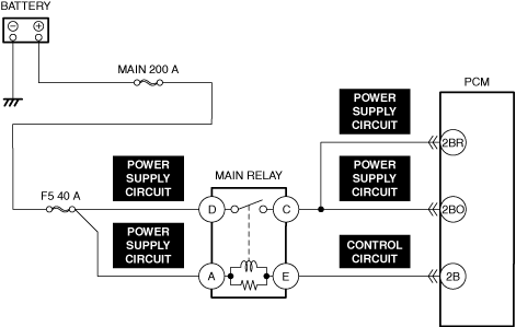
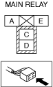
INSPECT MAIN RELAY POWER SUPPLY CIRCUIT FOR SHORT TO GROUND AND OPEN CIRCUIT
• Inspect the power supply circuit for an open circuit and short to ground. (See CIRCUIT INSPECTION.)
• Is the circuit normal?
|
Yes
|
Go to the next step.
|
|
No
|
Repair or replace the malfunctioning location and perform the repair completion verification.
|
||
|
7
|
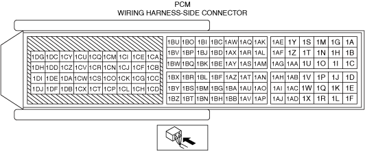
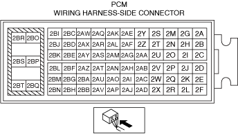
INSPECT PCM CONNECTOR FOR MALFUNCTION
• Inspect the applicable connector and terminal. (See CONNECTOR INSPECTION.)
• Are the connector and terminal normal?
|
Yes
|
Go to the next step.
|
|
No
|
Repair or replace the malfunctioning location and perform the repair completion verification.
|
||
|
8
|
INSPECT PCM POWER SUPPLY CIRCUIT FOR SHORT TO GROUND
• Inspect the applicable circuit for a short to ground. (See CIRCUIT INSPECTION.)
• Is the circuit normal?
|
Yes
|
Go to the next step.
|
|
No
|
Repair or replace the malfunctioning location and perform the repair completion verification.
|
||
|
9
|
INSPECT MAIN RELAY CONTROL CIRCUIT FOR SHORT TO GROUND
• Inspect the applicable circuit for a short to ground. (See CIRCUIT INSPECTION.)
• Is the circuit normal?
|
Yes
|
Go to the next step.
|
|
No
|
Repair or replace the malfunctioning location and perform the repair completion verification.
|
||
|
10
|
INSPECT PCM POWER SUPPLY CIRCUIT FOR OPEN CIRCUIT
• Inspect the applicable circuit for open circuit. (See CIRCUIT INSPECTION.)
• Is the circuit normal?
|
Yes
|
Go to the next step.
|
|
No
|
Repair or replace the malfunctioning location and perform the repair completion verification.
|
||
|
11
|
INSPECT MAIN RELAY CONTROL CIRCUIT FOR OPEN CIRCUIT
• Inspect the applicable circuit for open circuit. (See CIRCUIT INSPECTION.)
• Is the circuit normal?
|
Yes
|
Go to the next step.
|
|
No
|
Repair or replace the malfunctioning location and perform the repair completion verification.
|
||
|
12
|
INSPECT A/C CUT-OFF CONTROL SYSTEM OPERATION
• Perform the A/C Cut-off Control System Inspection. (See ENGINE CONTROL SYSTEM OPERATION INSPECTION [SKYACTIV-G (US)].)
• Does the A/C cut-off operation work properly?
|
Yes
|
Go to the next step.
|
|
No
|
Repair or replace the malfunctioning location and perform the repair completion verification.
|
||
|
13
|
DETERMINE IF MALFUNCTION CAUSE IS DRIVE-BY-WIRE CONTROL SYSTEM OR OTHER
• Will the engine run smoothly at part throttle?
|
Yes
|
Go to Step 15.
|
|
No
|
Go to the next step.
|
||
|
14
|
INSPECT DRIVE-BY-WIRE CONTROL SYSTEM OPERATION
• Perform the Electronic Control Throttle Operation Inspection. (See ENGINE CONTROL SYSTEM OPERATION INSPECTION [SKYACTIV-G (US)].)
• Does the drive-by-wire control system work properly?
|
Yes
|
Visually inspect the throttle body (damage/scratching).
• If there is any malfunction:
• If there is no malfunction:
|
|
No
|
Repair or replace the malfunctioning location and perform the repair completion verification.
|
||
|
15
|
INSPECT PURGE CONTROL SYSTEM OPERATION
• Perform the Purge Control System Inspection. (See PURGE SOLENOID VALVE INSPECTION [SKYACTIV-G (WITH CYLINDER DEACTIVATION (US))].) (See PURGE SOLENOID VALVE INSPECTION [SKYACTIV-G (WITHOUT CYLINDER DEACTIVATION (US))].)
• Does the purge solenoid valve work properly?
|
Yes
|
Go to the next step.
|
|
No
|
Repair or replace the malfunctioning location and perform the repair completion verification.
|
||
|
16
|
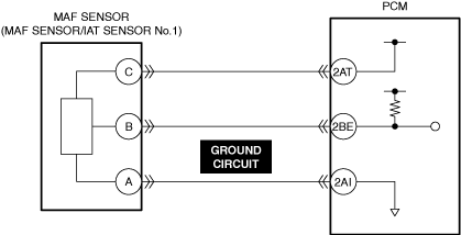
INSPECT MAF SENSOR GROUND CIRCUIT FOR OPEN CIRCUIT
• Inspect the applicable circuit for open circuit. (See CIRCUIT INSPECTION.)
• Is the circuit normal?
|
Yes
|
Go to the next step.
|
|
No
|
Repair or replace the malfunctioning location and perform the repair completion verification.
|
||
|
17
|
INSPECT PCM FOR POOR GROUND
• Verify the PCM ground point condition.
• Is there any ground point loose or lifting in the PCM?
|
Yes
|
Repair or replace the malfunctioning location and perform the repair completion verification.
|
|
No
|
Go to the next step.
|
||
|
18
|
INSPECT RELATED PART CONDITION
• Inspect the following:
• Is there any malfunction?
|
Yes
|
Repair or replace the malfunctioning location and perform the repair completion verification.
|
|
No
|
Go to the next step.
|
||
|
19
|
INSPECT FUEL PRESSURE (HIGH-SIDE)
• Start the engine and warm it up completely.
• Access the FUEL_PRES PID using the M-MDS at idle. (See PID/DATA MONITOR INSPECTION.)
• Is the FUEL_PRES PID value within specification?
Specification:
• Approx. 10 MPa {102 kgf/cm2, 1450 psi}
|
Yes
|
Go to Step 23.
|
|
No
|
Lower than specification:
• Inspect the following:
• If there is any malfunction:
• If there is no malfunction:
Higher than specification:
• Go to the next step.
|
||
|
20
|
DETERMINE IF MALFUNCTION CAUSE IS FUEL PRESSURE SENSOR OR HIGH PRESSURE FUEL PUMP
• Is the vehicle acceleration performance normal?
|
Yes
|
Go to the next step.
|
|
No
|
Go to Step 22.
|
||
|
21
|
INSPECT FUEL PRESSURE SENSOR FOR MALFUNCTION
• Inspect the applicable part. (See FUEL PRESSURE SENSOR INSPECTION [SKYACTIV-G (WITH CYLINDER DEACTIVATION (US))].) (See FUEL PRESSURE SENSOR INSPECTION [SKYACTIV-G (WITHOUT CYLINDER DEACTIVATION (US))].)
• Is the part normal?
|
Yes
|
Go to Step 23.
|
|
No
|
Replace the fuel distributor and perform the repair completion verification.
|
||
|
22
|
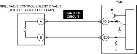
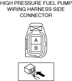
INSPECT SPILL VALVE CONTROL SOLENOID VALVE CONTROL CIRCUIT FOR SHORT TO GROUND
• Inspect the applicable circuit for a short to ground. (See CIRCUIT INSPECTION.)
• Is the circuit normal?
|
Yes
|
Replace the high pressure fuel pump and perform the repair completion verification.
|
|
No
|
Repair or replace the malfunctioning location and perform the repair completion verification.
|
||
|
23
|
INSPECT FUEL PRESSURE (LOW-SIDE)
• Connect the fuel pressure gauge between fuel pump and high pressure fuel pump.
• Measure the low side fuel pressure. (See FUEL LINE PRESSURE INSPECTION [SKYACTIV-G (WITH CYLINDER DEACTIVATION (US))].) (See FUEL LINE PRESSURE INSPECTION [SKYACTIV-G (WITHOUT CYLINDER DEACTIVATION (US))].)
• Is the low side fuel pressure within specification?
Specification:
• 475—555 kPa {4.85—5.65 kgf/cm2, 68.9—80.4 psi}
|
Yes
|
Go to the next step.
|
|
No
|
Inspect the following:
• Fuel line restriction
• Fuel filter clogged
|
||
|
24
|
INSPECT FUEL INJECTOR OPERATION
• Perform the Fuel Injector Operation Inspection. (See FUEL INJECTOR INSPECTION [SKYACTIV-G (WITH CYLINDER DEACTIVATION (US))].) (See FUEL INJECTOR INSPECTION [SKYACTIV-G (WITHOUT CYLINDER DEACTIVATION (US))].)
• Do the fuel injectors operate properly?
|
Yes
|
Go to the next step.
|
|
No
|
Repair or replace the malfunctioning location and perform the repair completion verification.
|
||
|
25
|
INSPECT ENGINE COMPRESSION
• Measure the compression pressure for each cylinder. (See COMPRESSION INSPECTION [SKYACTIV-G (WITH CYLINDER DEACTIVATION (US))].) (See COMPRESSION INSPECTION [SKYACTIV-G (WITHOUT CYLINDER DEACTIVATION (US))].)
• Are compression pressures within specification?
|
Yes
|
Go to Step 34.
|
|
No
|
Go to the next step.
|
||
|
26
|
INSPECT ELECTRIC VARIABLE VALVE TIMING DRIVER FOR MALFUNCTION
• Inspect the applicable part. (See ELECTRIC VARIABLE VALVE TIMING MOTOR/DRIVER INSPECTION [SKYACTIV-G (WITH CYLINDER DEACTIVATION (US))].) (See ELECTRIC VARIABLE VALVE TIMING MOTOR/DRIVER INSPECTION [SKYACTIV-G (WITHOUT CYLINDER DEACTIVATION (US))].)
• Is the part normal?
|
Yes
|
Go to the next step.
|
|
No
|
Repair or replace the malfunctioning location and perform the repair completion verification.
|
||
|
27
|
INSPECT ELECTRIC VARIABLE VALVE TIMING MOTOR FOR MALFUNCTION
• Inspect the applicable part. (See ELECTRIC VARIABLE VALVE TIMING MOTOR/DRIVER INSPECTION [SKYACTIV-G (WITH CYLINDER DEACTIVATION (US))].) (See ELECTRIC VARIABLE VALVE TIMING MOTOR/DRIVER INSPECTION [SKYACTIV-G (WITHOUT CYLINDER DEACTIVATION (US))].)
• Is the part normal?
|
Yes
|
Go to the next step.
|
|
No
|
Repair or replace the malfunctioning location and perform the repair completion verification.
|
||
|
28
|
INSPECT ELECTRIC VARIABLE VALVE TIMING ACTUATOR FOR MALFUNCTION
• Inspect the applicable part. (See ELECTRIC VARIABLE VALVE TIMING ACTUATOR INSPECTION [SKYACTIV-G (WITH CYLINDER DEACTIVATION (US))].) (See ELECTRIC VARIABLE VALVE TIMING ACTUATOR INSPECTION [SKYACTIV-G (WITHOUT CYLINDER DEACTIVATION (US))].)
• Is the part normal?
|
Yes
|
Go to the next step.
|
|
No
|
Repair or replace the malfunctioning location and perform the repair completion verification.
|
||
|
29
|
INSPECT HYDRAULIC VARIABLE VALVE TIMING CONTROL SYSTEM OPERATION
• Perform the Hydraulic Variable Valve Timing Control System Operation Inspection. (See OCV FOR HYDRAULIC VARIABLE VALVE TIMING SYSTEM INSPECTION [SKYACTIV-G (WITH CYLINDER DEACTIVATION (US))].) (See OIL CONTROL VALVE (OCV) INSPECTION [SKYACTIV-G (WITHOUT CYLINDER DEACTIVATION (US))].)
• Is there any malfunction?
|
Yes
|
Repair or replace the malfunctioning location and perform the repair completion verification.
|
|
No
|
Go to the next step.
|
||
|
30
|
INSPECT FOR MALFUNCTION DUE TO DEVIATED VALVE TIMING
• Inspect the valve timing (timing chain installation condition). (See TIMING CHAIN REMOVAL/INSTALLATION [SKYACTIV-G (WITH CYLINDER DEACTIVATION (US))].) (See TIMING CHAIN REMOVAL/INSTALLATION [SKYACTIV-G (WITHOUT CYLINDER DEACTIVATION (US))].)
• Is the valve timing normal?
|
Yes
|
Inspect for the following engine internal parts:
• Cylinder
• Piston ring
• Intake valve
• Exhaust valve
• Such as cylinder head gasket
|
|
No
|
Adjust the valve timing to the correct timing and perform the repair completion verification.
|
||
|
31
|
INSPECT IGNITION SYSTEM OPERATION
• Perform the Spark Test. (See SPARK INSPECTION [SKYACTIV-G (WITH CYLINDER DEACTIVATION (US))].) (See SPARK INSPECTION [SKYACTIV-G (WITHOUT CYLINDER DEACTIVATION (US))].)
• Is a strong blue spark visible at each cylinder?
|
Yes
|
Go to the next step.
|
|
No
|
Repair or replace the malfunctioning location and perform the repair completion verification.
|
||
|
32
|
INSPECT EXHAUST SYSTEM FOR RESTRICTION
• Inspect for restriction in the exhaust system and the TWC.
• Is there any restriction?
|
Yes
|
Repair or replace the malfunctioning location and perform the repair completion verification.
|
|
No
|
Go to the next step.
|
||
|
33
|
INSPECT IF MALFUNCTION CAUSE IS PCV VALVE OR INJECTOR DRIVER (PCM INTEGRATED)
• Inspect the PCV valve. (See POSITIVE CRANKCASE VENTILATION (PCV) VALVE INSPECTION [SKYACTIV-G (WITH CYLINDER DEACTIVATION (US))].) (See POSITIVE CRANKCASE VENTILATION (PCV) VALVE INSPECTION [SKYACTIV-G (WITHOUT CYLINDER DEACTIVATION (US))].)
• Is there any malfunction?
|
Yes
|
Replace the PCV valve and perform the repair completion verification.
|
|
No
|
Injector driver malfunction.
• Replace the PCM. (See PCM REMOVAL/INSTALLATION [SKYACTIV-G (WITH CYLINDER DEACTIVATION (US))].) (See PCM REMOVAL/INSTALLATION [SKYACTIV-G (WITHOUT CYLINDER DEACTIVATION (US))].)
If the problem remains, overhaul the engine and perform the repair completion verification.
|
||
|
Repair completion verification 1
|
VERIFY THAT VEHICLE IS REPAIRED
• Install/connect the part removed/disconnected during the troubleshooting procedure.
• Has the malfunction symptom been eliminated?
|
Yes
|
Complete the symptom troubleshooting. (Explain contents of repair to customer)
|
|
No
|
Refer to the controller area network (CAN) malfunction diagnosis flow to inspect for a CAN communication error.
• If the CAN communication is normal, perform the diagnosis from Step 1.
|
||
|
Repair completion verification 2
|
VERIFY IF MALFUNCTION IS CAUSED BY NOT PERFORMING PCM REPROGRAMMING
• Verify repair information and verify that there is a new calibration in the PCM.
• Is there a new calibration in the PCM?
|
Yes
|
Perform the PCM reprogramming and verify if the malfunction symptom was corrected.
• If the malfunction recurs, replace the PCM. (See PCM REMOVAL/INSTALLATION [SKYACTIV-G (WITH CYLINDER DEACTIVATION (US))].) (See PCM REMOVAL/INSTALLATION [SKYACTIV-G (WITHOUT CYLINDER DEACTIVATION (US))].)
|
|
No
|
Replace the PCM.
|