ENGINE CONTROL SYSTEM OPERATION INSPECTION [SKYACTIV-G (US)]
ENGINE CONTROL SYSTEM OPERATION INSPECTION [SKYACTIV-G (US)]
SM2565594
id0103s48916s6
Special Service Tool (SST)
|
MAZ-95-130-KT
Dual purpose diagnostic leak detector
|
 |
—
|
—
|
||
Drive-by-wire Control System Inspection
Load compensation inspection
1.Start the engine and let it idle.
2.Connect the M-MDS to the DLC-2.
3.Verify that DTC P0506:00 or P0507:00 is not displayed. (See DTC INSPECTION.)
-
• If DTC P0506:00 or P0507:00 is displayed, perform the DTC inspection. (See DTC P0506:00 [PCM (SKYACTIV-G)].) (See DTC P0507:00 [PCM (SKYACTIV-G)].)
4.Select the ENG_RPM PID.
-
Note
-
• Excludes temporary idle speed drop just after the loads are turned on.
5.Verify that the engine speed is within specification under each load condition.
-
• If the load condition is not as specified, inspect the following:
-
― A/C switch and related wiring harness system (A/C request signal is always on or off) (See A/C DOES NOT WORK SUFFICIENTLY [SKYACTIV-G].) (See A/C IS ALWAYS ON OR A/C COMPRESSOR RUNS CONTINUOUSLY [SKYACTIV-G].)― Electrical load― Charging system (See BATTERY INSPECTION [(US)].) (See GENERATOR INSPECTION [SKYACTIV-G (WITH CYLINDER DEACTIVATION (US))].) (See GENERATOR INSPECTION [SKYACTIV-G (WITHOUT CYLINDER DEACTIVATION (US))].)
-
-
Idle-up speed [SKYACTIV-G 2.0] (MTX: Neutral position, ATX: P, N position)
-
No load: 500—600 rpm (MTX), 550—650 rpm (ATX)A/C on: 650—800 rpmElectrical loads on: 600—750 rpm
-
Idle-up speed [SKYACTIV-G 2.5] (MTX: Neutral position, ATX: P, N position)
-
No load: 560—660 rpm (MTX), 550—650 rpm (ATX)A/C on: 650—800 rpmElectrical loads on: 600—750 rpm
Electronic Control Throttle Operation Inspection
1.Connect the M-MDS to the DLC-2.
2.Perform the KOEO or KOER self test. (See DTC INSPECTION.)
3.Verify that none of the following DTCs are displayed:
-
• P0122:00, P0123:00, P0222:00, P0223:00, P0638:00, P2101:00, P2107:00, P2109:00, P2110:00, P2112:00, P2119:00, P2122:00, P2123:00, P2127:00, P2128:00, P2135:00 and P2138:00
-
― If any one DTC is displayed, perform the DTC inspection. (See DTC TABLE [PCM (SKYACTIV-G (US))].)
-
4.Access the following PCM PIDs using the M-MDS. (See PID/DATA MONITOR INSPECTION.)
-
• THRO_ANG_ACT• THRO_ANG_COMD
5.With the accelerator pedal not depressed and with it depressed to the floor, verify that the data monitor item THRO_ANG_ACT value changes in conjunction with the THRO_ANG_COMD value.
-
• If this change cannot be verified, perform the Resistance Inspection for the throttle body. (See THROTTLE BODY INSPECTION [SKYACTIV-G (WITH CYLINDER DEACTIVATION (US))].) (See THROTTLE BODY INSPECTION [SKYACTIV-G (WITHOUT CYLINDER DEACTIVATION (US))].)
Brake override system operation inspection
-
Note
-
• If the brake override system operates normally after performing the following inspection, the PCM detects DTC P2299:00.
1.Start the engine and let it idle.
2.Verify that the engine speed becomes less than 1,200 rpm under the following conditions.
-
• Neutral (MTX)• N position (ATX)• Engine speed of 3,000 rpm or more with accelerator pedal depressed• Brake pedal depressed
-
― If the engine speed becomes approx. 1,200 rpm, clear the PCM DTC using the M-MDS. (System operation is normal.)― If the engine speed does not become approx. 1,200 rpm, inspect for the following parts, then repair or replace the malfunctioning part:
-
• APP sensor (See ACCELERATOR PEDAL POSITION (APP) SENSOR INSPECTION [SKYACTIV-G (WITH CYLINDER DEACTIVATION (US))].) (See ACCELERATOR PEDAL POSITION (APP) SENSOR INSPECTION [SKYACTIV-G (WITHOUT CYLINDER DEACTIVATION (US))].)• Neutral sensor (MTX) (See NEUTRAL SENSOR INSPECTION [SKYACTIV-G (WITH CYLINDER DEACTIVATION (US))].) (See NEUTRAL SENSOR INSPECTION [SKYACTIV-G (WITHOUT CYLINDER DEACTIVATION (US))].)• Brake switch (See BRAKE SWITCH INSPECTION.)• Communication between PCM and TCM (ATX) (See CONTROLLER AREA NETWORK (CAN) MALFUNCTION DIAGNOSIS FLOW [(US)].)
-
-
Fuel Cut Control System Inspection
-
Note
-
• This inspection has to be performed after the Fuel Injector Operation Inspection.
If data monitor function of M-MDS is used:
1.Warm up the engine and idle it.
2.Connect the M-MDS to the DLC-2.
3.Select the ENG_RPM and the FUEL_PULSE_WD PIDs. (See PID/DATA MONITOR INSPECTION.)
4.Monitor both PIDs while performing the following steps:
- (1)Depress the accelerator pedal and increase the ENG_RPM PID to 4,000 rpm.
- (2)Quickly release the accelerator pedal (brake pedal is not depressed) and verify that the FUEL_PULSE_WD PID is 0 msec, and 2—5 msec when the ENG_RPM PID drops below 1,200 rpm.
-
-
• If not as specified, inspect the following:
-
― ECT sensor No.1 and related wiring harness ECT sensor No.2 and related wiring harness (See ENGINE COOLANT TEMPERATURE (ECT) SENSOR INSPECTION [SKYACTIV-G (WITH CYLINDER DEACTIVATION (US))].) (See ENGINE COOLANT TEMPERATURE (ECT) SENSOR INSPECTION [SKYACTIV-G (WITHOUT CYLINDER DEACTIVATION (US))].)
-
-
If data monitor function of M-MDS is not used:
1.Warm up the engine and idle it.
2.Measure the fuel injector control signal wave profile using the oscilloscope while performing the following steps:
- (1)Depress the accelerator pedal and increase the engine speed to 4,000 rpm.
- (2)Quickly release the accelerator pedal (brake pedal is not depressed) and verify that the wave profile constant B+, and the wave appears when the engine speed drops below 1,200 rpm.
- (See PCM INSPECTION [SKYACTIV-G (WITH CYLINDER DEACTIVATION (US))].)(See PCM INSPECTION [SKYACTIV-G (WITHOUT CYLINDER DEACTIVATION (US))].)
-
• If not as specified, inspect the following:
-
― ECT sensor No.1 and related wiring harness ECT sensor No.2 and related wiring harness (See ENGINE COOLANT TEMPERATURE (ECT) SENSOR INSPECTION [SKYACTIV-G (WITH CYLINDER DEACTIVATION (US))].) (See ENGINE COOLANT TEMPERATURE (ECT) SENSOR INSPECTION [SKYACTIV-G (WITHOUT CYLINDER DEACTIVATION (US))].)
-
-
A/C Cut-off Control System Inspection
1.Start the engine.
2.Turn the A/C switch on.
3.Verify that the A/C compressor magnetic clutch actuates.
-
• If it does not actuate, perform the symptom troubleshooting “A/C DOES NOT WORK SUFFICIENTLY“. (See A/C DOES NOT WORK SUFFICIENTLY [SKYACTIV-G].)
4.Fully open the throttle valve and verify that the A/C compressor magnetic clutch does not actuate for 2—5 s.
-
• If it actuates, inspect the following:
-
― A/C relay (See RELAY INSPECTION.)― Open or short to ground in wiring harness and connectors (Battery—IG1 relay No.2—A/C relay—PCM terminal 2AF)― A/C related parts― APP1, APP2 PIDs
-
Related PIDs
|
PIDs |
Reference |
|---|---|
|
APP1
|
|
|
APP2
|
Evaporative Emission (EVAP) System Leak Inspection
acmzzw00000241
|
Safety precautions
-
• Use this equipment in the manner specified by the manufacturer.• Fully Understand operating procedures for this equipment.• Review, understand and complete the Initial set-up for this equipment.• Follow all safety precautions.
-
Caution
-
• Only use this equipment when the engine is turned off• Do not use turbo/high pressure in EVAP system• Never use high-pressure (left side) in a fuel tank of fuel vapor recovery system
• Do not leave a vehicle unattended while equipment is connected or operating.• Equipment operates on AC voltage.• Do not perform tests near a source of spark of ignition.• When working with the fuel system, work in a well-ventilated area.• Always wear the appropriate safety protection. Wear OSHA standard eye wear and protective gloves when using this equipment.-
Note
-
• Always visually inspect the fuel cap seal for cracks or damage. If there is a crack or any damage to the seal, replace the fuel cap and verify the system does not have any other leaks. Receiver assembly tools are available via eStore to test fuel caps.
-
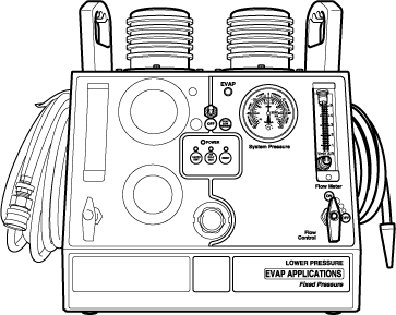
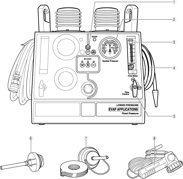
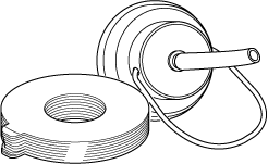
Dual purpose diagnostic leak detector (EVAP/low pressure) component parts
ac3uuw00002556
|
|
1
|
EVAP testing indicator
|
|
2
|
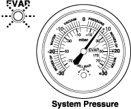
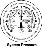
System pressure
|
|
3
|
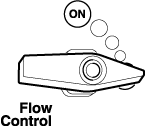
Flow meter
|
|
4
|
EVAP/low pressure vapor output hose
|
|
5
|
EVAP/low pressure flow control valve
|
|
6
|
Gas cap single thread [tool No.: 96-0092]
|
|
7
|
Universal filler neck connector [tool No.: 95-0011]
|
|
8
|
Halogen inspection light [tool No.: 96-0011]
|
Air only test
-
• Test the EVAP system using the decay or leak down testing method with “Air only test”.
-
Note
-
• Using the low-pressure or right side of the machine, determine if the system leaks by pressurizing the system with air using the Air only test.• On low-pressure, the fixed pressure is less than one half of one percent.• The air only test must be done first because the vapor test generates heat that can increase pressure and affect the accuracy of the pressure gauge.• Always perform the air only test before the vapor test.
-
1.Move the vehicle to a location where safety can be assured.
2.Ignition switched ON (engine off).
3.Access the following PIDs using the M-MDS. (See PCM INSPECTION [SKYACTIV-G (WITHOUT CYLINDER DEACTIVATION (US))].)(See PCM INSPECTION [SKYACTIV-G (WITH CYLINDER DEACTIVATION (US))].)
-
― EVAPCV
4.Remove the fuel-filler cap from the vehicle and clean the fuel-filler cap installation surface of the vehicle.
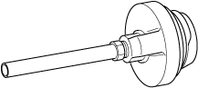
5.Install the gas cap single thread to the fuel-filler cap installation surface.
acmzzw00000243
|
-
Note
-
• If the gas cap single thread does not fit to the fuel-filler cap installation surface, use the universal filler neck connector.• EVAP test tools for older vehicles (1998—2013 MY) are available via eStore.
 acmzzw00000244
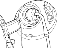
6.Insert the EVAP/low pressure vapor output hose nozzle into the gas cap single thread hose as shown in the figure.
acmzzw00000245
|
7.Toggle the power supply switch to the right to turn on the EVAP/low pressure testing (right side of tester) and verify that the green lamp turns on.
acmzzw00000246
|
8.Verify that the flow control valves for the EVAP/low pressure testing (right side of tester) and turbo/high pressure testing (left side of tester) are OFF.
acmzzw00000247
|
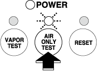
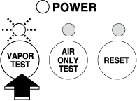
9.Press the [AIR ONLY TEST] button in the center of the tester and verify that the blue lamp turns on.
acmzzw00000248
|
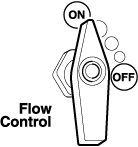
10.Turn the EVAP/low pressure flow control valve for the EVAP/low pressure testing (right side of tester) to ON to send air to the EVAP system.
acmzzw00000249
|
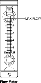
11.Verify that the flow meter for the EVAP/low pressure testing (right side of tester) indicates the maximum flow rate.
acmzzw00000250
|
12.Set the CV solenoid valve (simulation item: EVAPCV) to ON using the M-MDS.
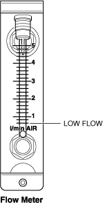
13. Verify that the indication of the flow meter for the EVAP/low pressure testing (right side of tester) decreases to the minimum flow rate.
acmzzw00000251
|
-
• If the flow meter indication does not decrease to the minimum flow rate, it means that there is leakage in the EVAP system. Perform the vapor test. (See Vapor test.)
14.Turn the EVAP/low pressure flow control valve for the EVAP/low pressure testing (right side of tester) to OFF.
acmzzw00000247
|
15.Read and record the value indicated by the system pressure gauge for the EVAP/low pressure testing (right side of tester).
acmzzw00000252
|
16.Leave the tester for 2 min.
17.Read the value indicated by the system pressure gauge again and check if there is any change from the value recorded in Step 15.
-
There is no change in the value
-
• The EVAP system is normal in the passage between the fuel-filler cap installation surface and the purge solenoid valve, or between the charcoal canister and the CV solenoid valve.
-
― Perform inspections of the following part because malfunctions can be considered with them.
-
-
There is change in the value
-
• The EVAP system has a malfunction between the fuel-filler cap and the purge solenoid valve, or between the charcoal canister and the CV solenoid valve.
-
― Perform the vapor test. (See Vapor test.)
-
Vapor test
1.Move the vehicle to a location where safety can be assured.
2.Ignition switched ON (engine off).
3.Access the following PIDs using the M-MDS. (See PCM INSPECTION [SKYACTIV-G (WITHOUT CYLINDER DEACTIVATION (US))].)(See PCM INSPECTION [SKYACTIV-G (WITH CYLINDER DEACTIVATION (US))].)
-
― EVAPCP
-
― EVAPCV
4.Press the [VAPOR TEST] button in the center of the tester and verify that the red lamp turns on.
acmzzw00000253
|
5.Turn the EVAP/low pressure flow control valve for the EVAP/low pressure testing (right side of tester) to ON.
acmzzw00000249
|
-
Note
-
• The vapor flow can be adjusted between the minimum and maximum levels.• The value indicated by the flow meter indicates the flow rate of the vapor supplied to the EVAP system.• The value indicated by the system pressure gauge indicates the internal pressure of the EVAP system.
6.Set the value for simulation item EVACP to 50% duty cycle.
7.Remove the evaporative hose inside the engine compartment. (See INTAKE-AIR SYSTEM REMOVAL/INSTALLATION [SKYACTIV-G (WITHOUT CYLINDER DEACTIVATION (US))].)(See INTAKE-AIR SYSTEM REMOVAL/INSTALLATION [SKYACTIV-G (WITH CYLINDER DEACTIVATION (US))].)
8.Verify that vapor comes out from the evaporative hose.
9.Set the CV solenoid valve (simulation item: EVAPCV) to ON using the M-MDS.
10.Set the value for simulation item EVACP to 0% duty cycle.
11.Leave for 2 min with the EVAP/low pressure flow control valve ON.
12.Monitor the indication of the flow meter for the EVAP/low pressure testing (right side of tester).
-
Flow meter value decreases to the minimum flow rate
-
• The EVAP system is normal in the passage between the fuel-filler cap installation surface and the purge solenoid valve, or between the charcoal canister and the CV solenoid valve.
-
― Perform inspections of the following part because malfunctions can be considered with them.
-
-
Flow meter value does not decrease to the minimum flow rate
-
• The EVAP system has a malfunction between the fuel-filler cap and the purge solenoid valve, or between the charcoal canister and the CV solenoid valve.
-
― Proceed to the next step.
-
13.Verify that vapor is leaking from the evaporative hose.
-
Vapor is leaking
-
• A malfunction can be considered with the purge solenoid valve. Perform the purge solenoid valve inspection. (See PURGE SOLENOID VALVE INSPECTION [SKYACTIV-G (WITHOUT CYLINDER DEACTIVATION (US))].)(See PURGE SOLENOID VALVE INSPECTION [SKYACTIV-G (WITH CYLINDER DEACTIVATION (US))].)
-
Vapor is not leaking
-
• Verify if vapor is leaking from between the fuel-filler cap and the purge solenoid valve using the halogen inspection light.
-
― If vapor is leaking, replace the malfunctioning part, and perform the Air only test again. (See Air only test.)
-