HARD TO START/LONG CRANK/ERRATIC START/ERRATIC CRANK [SKYACTIV-G]
HARD TO START/LONG CRANK/ERRATIC START/ERRATIC CRANK [SKYACTIV-G]
SM2334605
id0103s4889100
|
Troubleshooting item |
Hard to start/Long crank/Erratic start/Erratic crank |
|
|---|---|---|
|
Description
|
• Starter cranks engine at normal speed but engine requires excessive cranking time before starting.
• Battery is operating normally.
|
|
|
Possible cause
|
• Engine overheating
• PCM DTC is stored
• Erratic signal to PCM
• Improper operation of drive-by-wire control system
• Incorrect fuel injection timing
• Fuel injector malfunction
• Purge solenoid valve malfunction
• Contamination in MAF sensor
• Under the condition in which the engine starts and stops repeatedly while the vehicle is not driven, the fuel injected prior to complete ignition during engine start may drop into the oil pan from the cylinder and mix with the engine oil. The situation in which excess quantities of fuel continue to be injected due to an engine coolant temperature signal error is the same.
• Intermittent open circuit in PCM ground circuit
• Poor fuel quality
• Fuel leakage
• Air leakage from intake-air system
• Intake-air system restriction
• Vacuum leakage
• Improper engine oil viscosity
• Erratic signal from CKP sensor
• Erratic signal from CMP sensor
• Inadequate fuel pressure (high or low pressure side)
• Starting system malfunction
• Low engine compression
• Improper intake valve timing
• Improper exhaust valve timing
• Improper operation of electric variable valve timing control system
• Improper operation of hydraulic variable valve timing control system
• Ignition coil malfunction
• Spark plug malfunction
• Exhaust system and/or TWC restriction
• PCV valve malfunction
• Injector driver (built-into PCM) malfunction
|
|
|
Possible cause
|
|
|
 |
||
 |
||
 |
||
-
Caution
-
• Verify the malfunction symptom according to not only the PID value but also the symptom troubleshooting.
Related PIDs
|
PIDs |
Reference |
|---|---|
|
ECT
|
|
|
ECT_VOLT
|
|
|
ECT2
|
|
|
ECT2_VOLT
|
|
|
FUEL_PRES
|
|
|
LOAD_CALC
|
|
|
LONG_FUEL_TRIM
|
|
|
MAF
|
|
|
MAP
|
|
|
MAP_VOLT
|
|
|
A/F_SEN_CUR
|
|
|
HO2S_OUT_VOLT
|
|
|
ENG_RPM
|
|
|
SHRT_FUEL_TRIM
|
|
|
TP_RELAT
|
|
|
VSS
|
Diagnostic Procedure
|
Step |
Inspection |
Results |
Action |
|---|---|---|---|
|
1
|
DETERMINE IF MALFUNCTION CAUSE IS OVERHEATING OR OTHER
• Access the ECT PID using the M-MDS. (See PID/DATA MONITOR INSPECTION.)
• Is the ECT PID value less than 116 °C {241 °F} during driving?
|
Yes
|
Go to the next step.
|
|
No
|
The cause of this concern could be from the cooling system overheating.
• Perform the symptom troubleshooting “COOLING SYSTEM CONCERNS-OVERHEATING”. (See COOLING SYSTEM CONCERNS-OVERHEATING [SKYACTIV-G (US)].)
|
||
|
2
|
VERIFY PCM DTC
• Perform the DTC inspection for the PCM. (See DTC INSPECTION.)
• Are any DTCs displayed?
|
Yes
|
Repair the malfunctioning location according to the applicable DTC troubleshooting.
|
|
No
|
Go to the next step.
|
||
|
3
|
VERIFY CURRENT INPUT SIGNAL STATUS
• Access the following PIDs using the M-MDS: (See PID/DATA MONITOR INSPECTION.)
• Do the PIDs indicate the correct values under the malfunction condition? (See PID/DATA MONITOR TABLE [PCM (SKYACTIV-G (US))].)
|
Yes
|
Go to the next step.
|
|
No
|
ECT, ECT_VOLT, ECT2, ECT2_VOLT PIDs are not as specified:
• Inspect the ECT sensor No.1 and No.2. (See ENGINE COOLANT TEMPERATURE (ECT) SENSOR INSPECTION [SKYACTIV-G (WITH CYLINDER DEACTIVATION (US))].) (See ENGINE COOLANT TEMPERATURE (ECT) SENSOR INSPECTION [SKYACTIV-G (WITHOUT CYLINDER DEACTIVATION (US))].)
MAF PID is not as specified:
• Inspect the MAF sensor. (See MASS AIR FLOW (MAF) SENSOR INSPECTION [SKYACTIV-G (WITH CYLINDER DEACTIVATION (US))].) (See MASS AIR FLOW (MAF) SENSOR INSPECTION [SKYACTIV-G (WITHOUT CYLINDER DEACTIVATION (US))].)
MAP, MAP_VOLT PIDs are not as specified:
• Inspect the MAP sensor. (See MANIFOLD ABSOLUTE PRESSURE (MAP) SENSOR INSPECTION [SKYACTIV-G (WITH CYLINDER DEACTIVATION (US))].) (See MANIFOLD ABSOLUTE PRESSURE (MAP) SENSOR INSPECTION [SKYACTIV-G (WITHOUT CYLINDER DEACTIVATION (US))].)
A/F_SEN_CUR, SHRT_FUEL_TRIM, LONG_FUEL_TRIM PIDs are not as specified:
• Inspect the A/F sensor. (See AIR FUEL RATIO (A/F) SENSOR INSPECTION [SKYACTIV-G (WITH CYLINDER DEACTIVATION (US))].) (See AIR FUEL RATIO (A/F) SENSOR INSPECTION [SKYACTIV-G (WITHOUT CYLINDER DEACTIVATION (US))].)
HO2S_OUT_VOLT PID is not as specified:
• Inspect the HO2S. (See HEATED OXYGEN SENSOR (HO2S) INSPECTION [SKYACTIV-G (WITH CYLINDER DEACTIVATION (US))].) (See HEATED OXYGEN SENSOR (HO2S) INSPECTION [SKYACTIV-G (WITHOUT CYLINDER DEACTIVATION (US))].)
Repair or replace the malfunctioning location.
• If the malfunction remains:
|
||
|
4
|
DETERMINE IF MALFUNCTION CAUSE IS DRIVE-BY-WIRE CONTROL SYSTEM OR OTHER
• Will the engine run smoothly at part throttle?
|
Yes
|
Go to Step 6.
|
|
No
|
Go to the next step.
|
||
|
5
|
INSPECT DRIVE-BY-WIRE CONTROL SYSTEM OPERATION
• Perform the Electronic Control Throttle Operation Inspection. (See ENGINE CONTROL SYSTEM OPERATION INSPECTION [SKYACTIV-G (US)].)
• Does the drive-by-wire control system work properly?
|
Yes
|
Visually inspect the throttle body (damage/scratching).
• If there is any malfunction:
• If there is no malfunction:
|
|
No
|
Repair or replace the malfunctioning location and perform the repair completion verification.
|
||
|
6
|
INSPECT FUEL INJECTOR OPERATION
• Perform the Fuel Injector Operation Inspection. (See FUEL INJECTOR INSPECTION [SKYACTIV-G (WITH CYLINDER DEACTIVATION (US))].) (See FUEL INJECTOR INSPECTION [SKYACTIV-G (WITHOUT CYLINDER DEACTIVATION (US))].)
• Do the fuel injectors operate properly?
|
Yes
|
Go to the next step.
|
|
No
|
Repair or replace the malfunctioning location and perform the repair completion verification.
|
||
|
7
|
INSPECT PURGE CONTROL SYSTEM OPERATION
• Perform the Purge Control System Inspection. (See PURGE SOLENOID VALVE INSPECTION [SKYACTIV-G (WITH CYLINDER DEACTIVATION (US))].) (See PURGE SOLENOID VALVE INSPECTION [SKYACTIV-G (WITHOUT CYLINDER DEACTIVATION (US))].)
• Does the purge solenoid valve work properly?
|
Yes
|
Go to the next step.
|
|
No
|
Repair or replace the malfunctioning location and perform the repair completion verification.
|
||
|
8
|
INSPECT MAF SENSOR
• Inspect the MAF sensor for the following:
• Is there any malfunction?
|
Yes
|
Repair or replace the malfunctioning location and perform the repair completion verification.
|
|
No
|
Go to the next step.
|
||
|
9
|
INSPECT PCM FOR POOR GROUND
• Verify the PCM ground point condition.
• Is there any ground point loose or lifting in the PCM?
|
Yes
|
Repair or replace the malfunctioning location and perform the repair completion verification.
|
|
No
|
Go to the next step.
|
||
|
10
|
INSPECT RELATED PART CONDITION
• Inspect the following:
• Is there any malfunction?
|
Yes
|
Repair or replace the malfunctioning location and perform the repair completion verification.
|
|
No
|
Go to the next step.
|
||
|
11
|
INSPECT FUEL PRESSURE (HIGH-SIDE)
• Start the engine and warm it up completely.
• Access the FUEL_PRES PID using the M-MDS at idle. (See PID/DATA MONITOR INSPECTION.)
• Is the FUEL_PRES PID value within specification?
Specification:
• Approx. 3 MPa {31 kgf/cm2, 435 psi} (Thailand specs.)
• Approx. 10 MPa {102 kgf/cm2, 1450 psi} (except Thailand specs.)
|
Yes
|
Go to Step 15.
|
|
No
|
Lower than specification:
• Inspect the following:
• If there is any malfunction:
• If there is no malfunction:
Higher than specification:
• Go to the next step.
|
||
|
12
|
DETERMINE IF MALFUNCTION CAUSE IS FUEL PRESSURE SENSOR OR HIGH PRESSURE FUEL PUMP
• Is the vehicle acceleration performance normal?
|
Yes
|
Go to the next step.
|
|
No
|
Go to Step 14.
|
||
|
13
|
INSPECT FUEL PRESSURE SENSOR FOR MALFUNCTION
• Inspect the applicable part. (See FUEL PRESSURE SENSOR INSPECTION [SKYACTIV-G (WITH CYLINDER DEACTIVATION (US))].) (See FUEL PRESSURE SENSOR INSPECTION [SKYACTIV-G (WITHOUT CYLINDER DEACTIVATION (US))].)
• Is the part normal?
|
Yes
|
Go to Step 15.
|
|
No
|
Replace the fuel distributor and perform the repair completion verification.
|
||
|
14
|
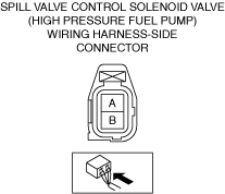
INSPECT SPILL VALVE CONTROL SOLENOID VALVE CONTROL CIRCUIT FOR SHORT TO GROUND
• Inspect the applicable circuit for a short to ground. (See CIRCUIT INSPECTION.)
• Is the circuit normal?
|
Yes
|
Replace the high pressure fuel pump and perform the repair completion verification.
|
|
No
|
Repair or replace the malfunctioning location and perform the repair completion verification.
|
||
|
15
|
INSPECT FUEL PRESSURE (LOW-SIDE)
• Connect the fuel pressure gauge between fuel pump and high pressure fuel pump.
• Measure the low side fuel pressure. (See FUEL LINE PRESSURE INSPECTION [SKYACTIV-G (WITH CYLINDER DEACTIVATION (US))].) (See FUEL LINE PRESSURE INSPECTION [SKYACTIV-G (WITHOUT CYLINDER DEACTIVATION (US))].)
• Is the low side fuel pressure within specification?
Specification:
• 475—555 kPa {4.85—5.65 kgf/cm2, 68.9—80.4 psi}
|
Yes
|
Go to the next step.
|
|
No
|
Inspect the following:
• Fuel line restriction
• Fuel filter clogged
|
||
|
16
|
INSPECT STARTING SYSTEM
• Inspect the starting system. (See STARTER INSPECTION [SKYACTIV-G (WITH CYLINDER DEACTIVATION (US))].) (See STARTER INSPECTION [SKYACTIV-G (WITHOUT CYLINDER DEACTIVATION (US))].)
• Does the starting system work properly?
|
Yes
|
Go to the next step.
|
|
No
|
Repair or replace the malfunctioning location and perform the repair completion verification.
|
||
|
17
|
INSPECT ENGINE COMPRESSION
• Measure the compression pressure for each cylinder. (See COMPRESSION INSPECTION [SKYACTIV-G (WITH CYLINDER DEACTIVATION (US))].) (See COMPRESSION INSPECTION [SKYACTIV-G (WITHOUT CYLINDER DEACTIVATION (US))].)
• Are compression pressures within specification?
|
Yes
|
Go to Step 23.
|
|
No
|
Go to the next step.
|
||
|
18
|
INSPECT ELECTRIC VARIABLE VALVE TIMING DRIVER FOR MALFUNCTION
• Inspect the applicable part. (See ELECTRIC VARIABLE VALVE TIMING MOTOR/DRIVER INSPECTION [SKYACTIV-G (WITH CYLINDER DEACTIVATION (US))].) (See ELECTRIC VARIABLE VALVE TIMING MOTOR/DRIVER INSPECTION [SKYACTIV-G (WITHOUT CYLINDER DEACTIVATION (US))].)
• Is the part normal?
|
Yes
|
Go to the next step.
|
|
No
|
Repair or replace the malfunctioning location and perform the repair completion verification.
|
||
|
19
|
INSPECT ELECTRIC VARIABLE VALVE TIMING MOTOR FOR MALFUNCTION
• Inspect the applicable part. (See ELECTRIC VARIABLE VALVE TIMING MOTOR/DRIVER INSPECTION [SKYACTIV-G (WITH CYLINDER DEACTIVATION (US))].) (See ELECTRIC VARIABLE VALVE TIMING MOTOR/DRIVER INSPECTION [SKYACTIV-G (WITHOUT CYLINDER DEACTIVATION (US))].)
• Is the part normal?
|
Yes
|
Go to the next step.
|
|
No
|
Repair or replace the malfunctioning location and perform the repair completion verification.
|
||
|
20
|
INSPECT ELECTRIC VARIABLE VALVE TIMING ACTUATOR FOR MALFUNCTION
• Inspect the applicable part. (See ELECTRIC VARIABLE VALVE TIMING ACTUATOR INSPECTION [SKYACTIV-G (WITH CYLINDER DEACTIVATION (US))].) (See ELECTRIC VARIABLE VALVE TIMING ACTUATOR INSPECTION [SKYACTIV-G (WITHOUT CYLINDER DEACTIVATION (US))].)
• Is the part normal?
|
Yes
|
Go to the next step.
|
|
No
|
Repair or replace the malfunctioning location and perform the repair completion verification.
|
||
|
21
|
INSPECT HYDRAULIC VARIABLE VALVE TIMING CONTROL SYSTEM OPERATION
• Perform the Hydraulic Variable Valve Timing Control System Operation Inspection. (See OCV FOR HYDRAULIC VARIABLE VALVE TIMING SYSTEM INSPECTION [SKYACTIV-G (WITH CYLINDER DEACTIVATION (US))].) (See OIL CONTROL VALVE (OCV) INSPECTION [SKYACTIV-G (WITHOUT CYLINDER DEACTIVATION (US))].)
• Is there any malfunction?
|
Yes
|
Repair or replace the malfunctioning location and perform the repair completion verification.
|
|
No
|
Go to the next step.
|
||
|
22
|
INSPECT FOR MALFUNCTION DUE TO DEVIATED VALVE TIMING
• Inspect the valve timing (timing chain installation condition). (See TIMING CHAIN REMOVAL/INSTALLATION [SKYACTIV-G (WITH CYLINDER DEACTIVATION (US))].) (See TIMING CHAIN REMOVAL/INSTALLATION [SKYACTIV-G (WITHOUT CYLINDER DEACTIVATION (US))].)
• Is the valve timing normal?
|
Yes
|
Inspect for the following engine internal parts:
• Cylinder
• Piston ring
• Intake valve
• Exhaust valve
• Such as cylinder head gasket
|
|
No
|
Adjust the valve timing to the correct timing and perform the repair completion verification.
|
||
|
23
|
INSPECT IGNITION SYSTEM OPERATION
• Perform the Spark Test. (See SPARK INSPECTION [SKYACTIV-G (WITH CYLINDER DEACTIVATION (US))].) (See SPARK INSPECTION [SKYACTIV-G (WITHOUT CYLINDER DEACTIVATION (US))].)
• Is a strong blue spark visible at each cylinder?
|
Yes
|
Go to the next step.
|
|
No
|
Repair or replace the malfunctioning location and perform the repair completion verification.
|
||
|
24
|
INSPECT EXHAUST SYSTEM FOR RESTRICTION
• Inspect for restriction in the exhaust system and the TWC.
• Is there any restriction?
|
Yes
|
Repair or replace the malfunctioning location and perform the repair completion verification.
|
|
No
|
Go to the next step.
|
||
|
25
|
INSPECT IF MALFUNCTION CAUSE IS PCV VALVE OR INJECTOR DRIVER (PCM INTEGRATED)
• Inspect the PCV valve. (See POSITIVE CRANKCASE VENTILATION (PCV) VALVE INSPECTION [SKYACTIV-G (WITH CYLINDER DEACTIVATION (US))].) (See POSITIVE CRANKCASE VENTILATION (PCV) VALVE INSPECTION [SKYACTIV-G (WITHOUT CYLINDER DEACTIVATION (US))].)
• Is there any malfunction?
|
Yes
|
Replace the PCV valve and perform the repair completion verification.
|
|
No
|
Injector driver malfunction.
• Replace the PCM. (See PCM REMOVAL/INSTALLATION [SKYACTIV-G (WITH CYLINDER DEACTIVATION (US))].) (See PCM REMOVAL/INSTALLATION [SKYACTIV-G (WITHOUT CYLINDER DEACTIVATION (US))].)
If the problem remains, overhaul the engine and perform the repair completion verification.
|
||
|
Repair completion verification 1
|
VERIFY THAT VEHICLE IS REPAIRED
• Install/connect the part removed/disconnected during the troubleshooting procedure.
• Has the malfunction symptom been eliminated?
|
Yes
|
Complete the symptom troubleshooting. (Explain contents of repair to customer)
|
|
No
|
Refer to the controller area network (CAN) malfunction diagnosis flow to inspect for a CAN communication error.
• If the CAN communication is normal, perform the diagnosis from Step 1.
|
||
|
Repair completion verification 2
|
VERIFY IF MALFUNCTION IS CAUSED BY NOT PERFORMING PCM REPROGRAMMING
• Verify repair information and verify that there is a new calibration in the PCM.
• Is there a new calibration in the PCM?
|
Yes
|
Perform the PCM reprogramming and verify if the malfunction symptom was corrected.
• If the malfunction recurs, replace the PCM. (See PCM REMOVAL/INSTALLATION [SKYACTIV-G (WITH CYLINDER DEACTIVATION (US))].) (See PCM REMOVAL/INSTALLATION [SKYACTIV-G (WITHOUT CYLINDER DEACTIVATION (US))].)
|
|
No
|
Replace the PCM.
|