CIRCUIT INSPECTION
CIRCUIT INSPECTION
SM2337319
id990200000700
-
Caution
-
• Disconnect the ground plate when servicing the following M Hybrid related parts. Otherwise, they could be damaged.
-
― Integrated starter generator (ISG)― M Hybrid battery― DC-DC converter (M Hybrid)― Seat warmer control unit (with M Hybrid, seat warmer system, and without position memory system)― Position memory control module (with M Hybrid and position memory system)― Front seat (driver’s side) (with M Hybrid and seat warmer system)
-
Circuit Inspection Table
|
Item |
Reference |
|---|---|
|
Inspection for Short to Ground and Open Circuit in Power Supply Circuit
|
|
|
Inspection for Short to Ground in Circuit
|
|
|
Inspection for Short to Power Supply in Circuit
|
|
|
Inspection for Open Circuit in Circuit
|
|
|
Inspection for Short Circuit in Circuits
|
Inspection for Short to Ground and Open Circuit in Power Supply Circuit
1.Disconnect the negative battery terminal. (See NEGATIVE BATTERY TERMINAL DISCONNECTION/CONNECTION [(US)].)
2.Disconnect the ground plate. (For servicing M Hybrid related parts)
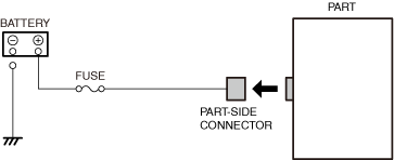
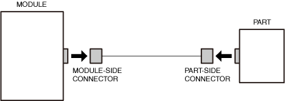
3.Disconnect the connector on the part side of the circuit to be inspected.
am3zzw00024477
|
-
Note
-
• For the connector disconnection procedure, refer to the removal/installation procedure for each part.
4.Connect the ground plate. (For servicing M Hybrid related parts)
5.Connect the negative battery terminal. (See NEGATIVE BATTERY TERMINAL DISCONNECTION/CONNECTION [(US)].)
6.Switch the ignition ACC (for ACC power supply circuit) or ON (engine off or on) (for IG1 power supply circuit).
7.Measure the voltage at the applicable part-side connector terminal.
atsvuw00000079
|
-
If voltage is B+:
-
• There is no short to ground in the circuit or an open circuit, therefore the inspection is completed.
-
If voltage is less than B+:
-
• To specify the malfunctioning location, go to the next step.
8.Inspect the fuse.
-
If the fuse is blown (short to ground):
-
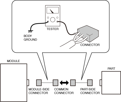
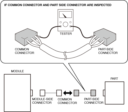
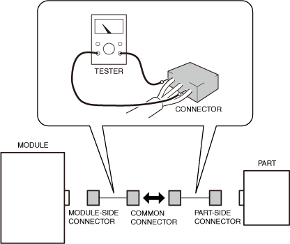
• Refer to the wiring diagram and verify if there is a common connector between the applicable circuits.
-
If there is a common connector:
-
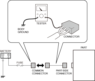
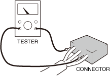
― Switch the ignition off.― Disconnect the negative battery terminal. (See NEGATIVE BATTERY TERMINAL DISCONNECTION/CONNECTION [(US)].)― Disconnect the ground plate. (For servicing M Hybrid related parts)― Disconnect the common connector and inspect the connector and terminal. (See CONNECTOR INSPECTION.)
 am3zzw00024478― Inspect each common connector for continuity between the applicable terminal and body ground to determine the malfunctioning location.
-
• Repair or replace the vehicle wiring harness which is shorted to ground.• Replace the blown fuse.
-
-
If there is no common connector:
-
― Repair or replace the vehicle wiring harness.― Replace the blown fuse.
-
-
If the fuse is damaged:
-
• Replace the damaged fuse.
-
If the fuse is normal (open circuit):
-
• Refer to the wiring diagram and verify if there is a common connector between the applicable circuits.
-
If there is a common connector:
-
― Switch the ignition off.― Disconnect the negative battery terminal. (See NEGATIVE BATTERY TERMINAL DISCONNECTION/CONNECTION [(US)].)― Disconnect the ground plate. (For servicing M Hybrid related parts)― Disconnect the common connector and inspect the connector and terminal. (See CONNECTOR INSPECTION.)am3zzw00024479― Inspect each common connector for continuity between the applicable terminals to determine the malfunctioning location.
-
• Repair or replace the vehicle wiring harness which has an open circuit.
-
-
If there is no common connector:
-
― Repair or replace the vehicle wiring harness.
-
Inspection for Short to Ground in Circuit
1.Disconnect the negative battery terminal. (See NEGATIVE BATTERY TERMINAL DISCONNECTION/CONNECTION [(US)].)
2.Disconnect the ground plate. (For servicing M Hybrid related parts)
3.Disconnect the connector on the module side and the connector on the part side of the circuit to be inspected.
atsvuw00000082
|
-
Note
-
• For the connector disconnection procedure, refer to the removal/installation procedure for each part.
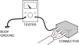
4.Inspect for continuity between the applicable terminal of the module-side or part-side connector and body ground.
atsvuw00000079
|
-
If there is continuity:
-
• To specify the malfunctioning location, go to the next step.
-
If there is no continuity:
-
• There is no short to ground in the circuit, therefore the inspection is completed.
5.Refer to the wiring diagram and verify if there is a common connector between the applicable circuits.
-
If there is a common connector:
-
• Disconnect the common connector and inspect the connector and terminal. (See CONNECTOR INSPECTION.)atsvuw00000083• Inspect each common connector for continuity to determine the malfunctioning location.
-
― Repair or replace the vehicle wiring harness which is shorted to ground.
-
-
If there is no common connector:
-
• Repair or replace the vehicle wiring harness.
Inspection for Short to Power Supply in Circuit
1.Disconnect the negative battery terminal. (See NEGATIVE BATTERY TERMINAL DISCONNECTION/CONNECTION [(US)].)
2.Disconnect the ground plate. (For servicing M Hybrid related parts)
3.Disconnect the connector on the module side and the connector on the part side of the circuit to be inspected.
atsvuw00000082
|
-
Note
-
• For the connector disconnection procedure, refer to the removal/installation procedure for each part.
4.Connect the ground plate. (For servicing M Hybrid related parts)
5.Connect the negative battery terminal. (See NEGATIVE BATTERY TERMINAL DISCONNECTION/CONNECTION [(US)].)
6.Switch the ignition ON (engine off or on).
7.Measure the voltage at the applicable terminal of the module-side or part-side connector.
atsvuw00000079
|
-
If voltage exceeds 0 V:
-
• To specify the malfunctioning location, go to the next step.
-
If voltage is 0 V:
-
• There is no short to power supply in the circuit, therefore the inspection is completed.
8.Refer to the wiring diagram and verify if there is a common connector between the applicable circuits.
-
If there is a common connector:
-
• Switch the ignition off.• Disconnect the negative battery terminal. (See NEGATIVE BATTERY TERMINAL DISCONNECTION/CONNECTION [(US)].)• Disconnect the ground plate. (For servicing M Hybrid related parts)• Disconnect the common connector and inspect the connector and terminal. (See CONNECTOR INSPECTION.)atsvuw00000083• Measure the voltage at each common connector to determine the malfunctioning location.
-
― Repair or replace the vehicle wiring harness which is shorted to the power supply.
-
-
If there is no common connector:
-
• Repair or replace the vehicle wiring harness.
Inspection for Open Circuit in Circuit
Circuit between module and part
1.Disconnect the negative battery terminal. (See NEGATIVE BATTERY TERMINAL DISCONNECTION/CONNECTION [(US)].)
2.Disconnect the ground plate. (For servicing M Hybrid related parts)
3.Disconnect the connector on the module side and the connector on the part side of the circuit to be inspected.
atsvuw00000082
|
-
Note
-
• For the connector disconnection procedure, refer to the removal/installation procedure for each part.
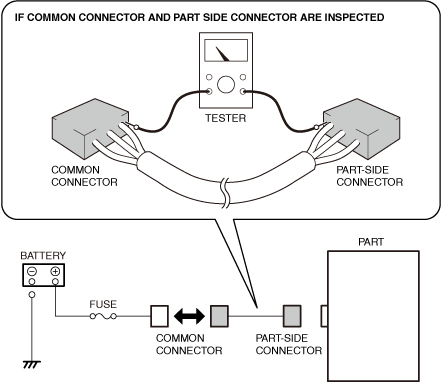
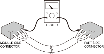
4.Inspect for continuity between the applicable terminals of the module-side connector and the part-side connector.
atsvuw00000084
|
-
Note
-
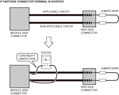
• If the inspection is difficult due to the distance between the module-side and part-side connectors being too far, the inspection can be performed using only one of the connectors by shorting one of the connector terminals using a jumper wire.atsvuw00000085
-
If there is continuity:
-
• There is no open circuit in the circuit, therefore the inspection is completed.
-
If there is no continuity:
-
• To specify the malfunctioning location, go to the next step.
5.Refer to the wiring diagram and verify if there is a common connector between the applicable circuits.
-
If there is a common connector:
-
• Disconnect the common connector and inspect the connector and terminal. (See CONNECTOR INSPECTION.)am3zzw00027664• Inspect each common connector for continuity to determine the malfunctioning location.
-
― Repair or replace the vehicle wiring harness which has an open circuit.
-
-
If there is no common connector:
-
• Repair or replace the vehicle wiring harness.
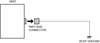
Circuit between part and body ground
1.Disconnect the negative battery terminal. (See NEGATIVE BATTERY TERMINAL DISCONNECTION/CONNECTION [(US)].)
2.Disconnect the ground plate. (For servicing M Hybrid related parts)
3.Disconnect the connector on the part side of the circuit to be inspected.
atsvuw00000087
|
-
Note
-
• For the connector disconnection procedure, refer to the removal/installation procedure for each part.
4.Inspect for continuity between the part-side connector applicable terminal and body ground.
atsvuw00000079
|
-
If there is continuity:
-
• There is no open circuit in the circuit, therefore the inspection is completed.
-
If there is no continuity:
-
• To specify the malfunctioning location, go to the next step.
5.Inspect for loose or lifting ground point.
-
If there is any malfunction:
-
• Repair or replace the malfunctioning part.
-
If there is no malfunction:
-
• Go to the next step.
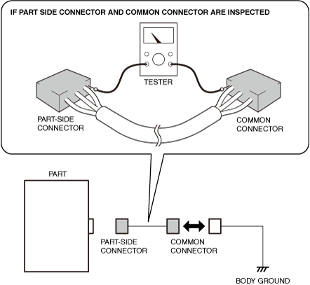
6.Refer to the wiring diagram and verify if there is a common connector between the applicable circuits.
-
If there is a common connector:
-
• Disconnect the common connector and inspect the connector and terminal. (See CONNECTOR INSPECTION.)• Inspect each common connector for continuity to determine the malfunctioning location.am3zzw00027665
-
― Repair or replace the vehicle wiring harness which has an open circuit.
-
-
If there is no common connector:
-
• Repair or replace the vehicle wiring harness.
Inspection for Short Circuit in Circuits
1.Disconnect the negative battery terminal. (See NEGATIVE BATTERY TERMINAL DISCONNECTION/CONNECTION [(US)].)
2.Disconnect the ground plate. (For servicing M Hybrid related parts)
3.Disconnect the connector on the module side and the connector on the part side of the circuit to be inspected.
atsvuw00000082
|
-
Note
-
• For the connector disconnection procedure, refer to the removal/installation procedure for each part.
4.Inspect for continuity between the applicable terminals of the module-side or part-side connector.
atsvuw00000089
|
-
If there is continuity:
-
• To specify the malfunctioning location, go to the next step.
-
If there is no continuity:
-
• There is no short between circuits, therefore the inspection is completed.
5.Refer to the wiring diagram and verify if there is a common connector between the applicable circuits.
-
If there is a common connector:
-
• Disconnect the common connector and inspect the connector and terminal. (See CONNECTOR INSPECTION.)• Inspect each common connector for continuity to determine the malfunctioning location.atsvuw00000090
-
― Repair or replace the vehicle wiring harness which is shorted.
-
-
If there is no common connector:
-
• Repair or replace the vehicle wiring harness.