DTC P0442:00, P0455:00 OR P0456:00 [PCM (SKYACTIV-G)]
DTC P0442:00, P0455:00 OR P0456:00 [PCM (SKYACTIV-G)]
SM2334487
id0102t4500200
-
Note
-
• To determine the malfunctioning part, proceed with the diagnostics from “Function Inspection Using M-MDS”.
Details On DTCs
|
Description |
P0442:00 • Evaporative gas leakage (leakage amount: low)
P0455:00 • Evaporative gas leakage (leakage amount: large)
P0456:00 • Evaporative gas leakage (leakage amount: extremely low)
|
|
|---|---|---|
|
Detection condition
|
Determination conditions
|
P0442:00
• Hole of 0.04 in (1.0 mm) or more in evaporative gas passage
|
|
P0455:00
• Hole of 0.09 in (2.25 mm) or more in evaporative gas passage
|
||
|
P0456:00
• Hole of 0.02 in (0.5 mm) or more in evaporative gas passage
|
||
|
Preconditions
|
P0442:00 and P0455:00
• Evaporative gas flow amount: Exceeds 10,000 cm3/min or fuel tank vacuum is high
• Fuel tank pressure: −4,340.2—4,030.1 Pa {−442.57—410.95 kgf/m2, −0.62949—0.58452 psi} *1
• IAT sensor No.1: 4.44—43.33 °C {40.0—109.9 °F} *1
• Vehicle speed: 64—145 km/h {40.0—90.0 mph} *1
• Barometric pressure: 72.23 kPa {0.7365 kgf/cm2, 10.48 psi} or more *1
• Period ignition is switched off before engine starts: 210 min or more
• Fuel level in fuel tank: 15—85 % *1
• Minimum value of intake manifold vacuum: 4 kPa {0.04 kgf/cm2, 0.6 psi} or more
• Minimum value of intake air amount: more than 2 g/sec
• Battery voltage: more than 11 V *1
• The following DTCs are not detected:
P0456:00
• Fuel level in fuel tank: 15—85 % *1
• Period ignition is switched off before engine starts: 210 min or more
• Barometric pressure: 72.23 kPa {0.7365 kgf/cm2, 10.48 psi} or more *1
• Time elapsed from engine start: 15—90 min
• Desired ambient air temperature: 4.44—37.78 °C {40.0—100.0 °F} *1
• The following DTCs are not detected:
*1: Standard can be verified by displaying PIDs using M-MDS
|
|
|
Malfunction determination period
|
• 75 s period
|
|
|
Drive cycle
|
• 2
|
|
|
Self test type
|
• CMDTC self test
|
|
|
Sensor used
|
• Fuel tank pressure sensor
|
|
|
Fail-safe function
|
• Not applicable
|
|
|
Vehicle status when DTCs are output
|
• Heating is ineffective after engine is started
|
|
|
Possible cause
|
• Missing or loose fuel filler cap
• Fuel filler cap malfunction
• Fuel tank pressure sensor malfunction
• CV solenoid valve malfunction
• Purge solenoid valve malfunction
• Evaporative gas passage malfunction
• Pressure control valve malfunction
• Charcoal canister main malfunction
• Charcoal canister sub malfunction
• Catch tank malfunction
• Fuel pump unit loose
• Fuel tank malfunction
• PCM malfunction
|
|
System Wiring Diagram
• Not applicable
Function Explanation (DTC Detection Outline)
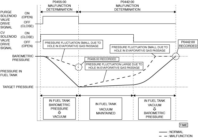
• The pressure change of the evaporative gas passage is measured using barometric pressure and intake manifold vacuum to detect evaporative gas leakage. The PCM introduces barometric pressure or intake manifold vacuum into the evaporative gas passage by opening/closing the purge solenoid valve and CV solenoid valve, and measures the pressure change using the fuel tank pressure sensor.
P0455:00
• The PCM closes the CV solenoid valve while the vehicle is being driven, and seals the fuel tank. The PCM introduces intake manifold vacuum into the fuel tank and measures the pressure change of the fuel tank using the fuel tank pressure sensor by opening the purge solenoid valve after sealing the fuel tank. If the pressure of the fuel tank does not reach the target value after the specified time has elapsed since the pressure was measured, the PCM determines that there is an evaporative gas leakage. If the PCM determines that refueling is not performed before the engine starts according to the result of the refuel determination, DTC P0455:00 is stored (if the PCM determines that refueling is performed, DTC P0457:00 is stored).
• If the fuel tank level increases after the engine starts, the PCM determines that refueling was performed by comparing the fuel tank level before one drive cycle with the fuel tank level after engine start.
P0442:00
• The PCM closes the purge solenoid valve after diagnosing (normal) DTC P0455:00, and seals the fuel tank. The pressure change of the fuel tank is measured by the fuel tank pressure sensor after the fuel tank is sealed. The PCM determines a temporary malfunction if the pressure change is the specified value or more after the specified time has elapsed since the pressure was measured. If the CV solenoid valve is open after determining a temporary malfunction and the pressure change (increase) of the fuel tank is the specified value or less, the PCM determines that there is an evaporative gas leakage and a DTC is stored.
am3zzw00033562
|
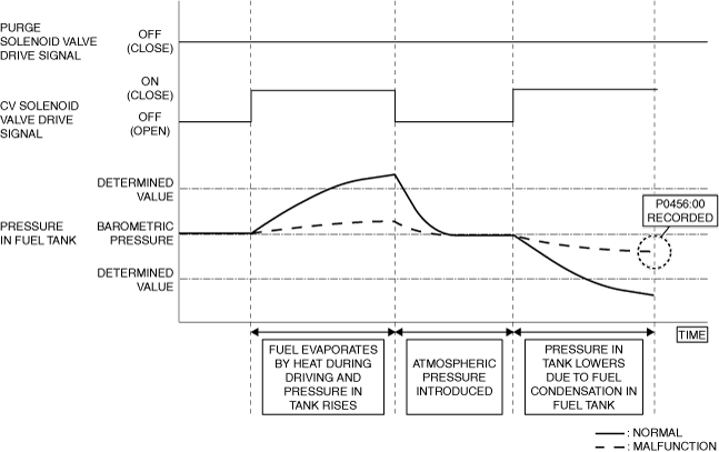
P0456:00
• After the engine stops with the preconditions met, the PCM closes the CV solenoid valve and seals the fuel tank. The pressure change of the fuel tank is measured by the fuel tank pressure sensor after the fuel tank is sealed. The PCM determines a temporary malfunction when the pressure change is the specified value or less after the specified time has elapsed since the pressure was measured. If the CV solenoid valve is open after determining a temporary malfunction and the pressure change of the fuel tank is the specified value or less, the PCM determines that there is an evaporative gas leakage and a DTC is stored.
am3zzw00033563
|
Repeatability Verification Procedure
P0442:00 and P0455:00
1. Set the remaining fuel quantity in the fuel tank between 30—85 %.
2. Start the engine and switch the ignition off after 5 s have elapsed.
3. Leave the vehicle for 6 hours or more.
4. Start the engine and leave it idling for 2 min.
5. Drive the vehicle for 30 min at a speed of 68 km/h {42 mph} or more (to increase temperature in fuel tank and generate evaporative gas).
-
Note
-
• If driving the vehicle for 30 min at a speed of 68 km/h {42 mph} or more is not feasible, the vehicle can be driven for a continuous 15 min or more with the engine coolant temperature at 80 °C {176 °F} or more.
P0456:00
1. Set the remaining fuel quantity in the fuel tank between 30—85 %.
2. Verify that OBD-II information (such as freeze frame data) has been obtained and recorded.
3. Clear the DTC from the PCM memory using the M-MDS. (See CLEARING DTC.)
4. Start the engine and switch the ignition off after 5 s have elapsed.
5. Leave the vehicle for 6 hours or more.
6. Start the engine and leave it idling for 2 min.
7. Drive the vehicle for 30 min at a speed of 50 km/h {31 mph} or more (to increase temperature in fuel tank and generate evaporative gas).
-
Note
-
• If driving the vehicle for 30 min at a speed of 50 km/h {31 mph} or more is not feasible, the vehicle can be driven for a continuous 15 min or more with the engine coolant temperature at 80 °C {176 °F} or more.
8. Stop the engine.
9. Leave the vehicle for 1 hours or more.
PID Item/Simulation Item Used In Diagnosis
PID/DATA monitor item table
|
PIDs |
Reference |
|---|---|
|
BARO
|
|
|
PRG_DUTY
|
|
|
CSTR_VENT_SOL_DUTY
|
|
|
FUEL_CAP_LAMP
|
|
|
FTP
|
Function Inspection Using M-MDS
|
Step |
Inspection |
Results |
Action |
|---|---|---|---|
|
1
|
PURPOSE: VERIFY RELATED REPAIR INFORMATION OR SERVICE INFORMATION AVAILABILITY
• Verify related Service Bulletins, on-line repair information, or Service Information availability.
• Is any related Information available?
|
Yes
|
Perform repair or diagnosis according to the available information.
• If the vehicle is not repaired, go to the next step.
|
|
No
|
Go to the next step.
|
||
|
2
|
PURPOSE: RECORD VEHICLE STATUS WHEN DTC WAS DETECTED TO UTILIZE WITH REPEATABILITY VERIFICATION
• Record the freeze frame data/snapshot data and diagnostic monitoring test results (EVAP system related).
|
—
|
Go to the next step.
|
|
3
|
PURPOSE: VERIFY IF DIAGNOSTIC RESULT IS AFFECTED BY MALFUNCTION OF CONTROL PART REQUIRED FOR DIAGNOSIS
• Perform the DTC inspection for the PCM. (See DTC INSPECTION.)
• Are any of the following DTCs displayed?
|
Yes
|
Repair the malfunctioning location according to the applicable DTC troubleshooting.
|
|
No
|
P0442:00, P0455:00 or P0456:00 is diagnosed:
• Go to the next step.
|
||
|
4
|
PURPOSE: VERIFY FUEL FILLER CAP MALFUNCTION
• Access the FUEL_CAP_LAMP PID using the M-MDS. (See PID/DATA MONITOR INSPECTION.)
• Is the FUEL_CAP_LAMP PID value Yes(True)?
|
Yes
|
Go to Troubleshooting Diagnostic Procedure to perform the procedure from Step 1.
|
|
No
|
Go to the next step.
|
||
|
5
|
PURPOSE: SPECIFY LOCATION OF EVAPORATIVE GAS LEAKAGE (FUEL TANK SIDE)
• Disconnect the evaporative hose of the following: (See QUICK RELEASE CONNECTOR (EMISSION SYSTEM) REMOVAL/INSTALLATION [SKYACTIV-G (WITH CYLINDER DEACTIVATION (US))].) (See QUICK RELEASE CONNECTOR (EMISSION SYSTEM) REMOVAL/INSTALLATION [SKYACTIV-G (WITHOUT CYLINDER DEACTIVATION (US))].)
• Plug the disconnected evaporative hose.
• Open the fuel-filler cap.
• Access the following PIDs using the M-MDS: (See PID/DATA MONITOR INSPECTION.)
• Does the FTP PID value correspond to the BARO PID value?
|
Yes
|
Go to the next step.
|
|
No
|
Go to Troubleshooting Diagnostic Procedure to perform the procedure from Step 3.
|
||
|
6
|
PURPOSE: SPECIFY LOCATION OF EVAPORATIVE GAS LEAKAGE (CHARCOAL CANISTER SIDE)
• Reconnect all the removed parts.
• Disconnect the evaporative hose of the following: (See QUICK RELEASE CONNECTOR (EMISSION SYSTEM) REMOVAL/INSTALLATION [SKYACTIV-G (WITH CYLINDER DEACTIVATION (US))].) (See QUICK RELEASE CONNECTOR (EMISSION SYSTEM) REMOVAL/INSTALLATION [SKYACTIV-G (WITHOUT CYLINDER DEACTIVATION (US))].)
• Plug the evaporative hoses (purge solenoid valve side and CV solenoid valve side).
• Open the fuel-filler cap.
• Access the following PIDs using the M-MDS: (See PID/DATA MONITOR INSPECTION.)
• Does the FTP PID value correspond to the BARO PID value?
|
Yes
|
Go to the next step.
|
|
No
|
Go to Troubleshooting Diagnostic Procedure to perform the procedure from Step 6.
|
||
|
7
|
PURPOSE: DETERMINE IF MALFUNCTION CAUSED BY CONTROL PART (PURGE SOLENOID VALVE) REQUIRED FOR DIAGNOSIS
• Reconnect all the removed parts.
• Start the engine and idle it.
• Access the PRG_DUTY PID using the M-MDS. (See PID/DATA MONITOR INSPECTION.)
• Is the PRG_DUTY PID value normal? (See PID/DATA MONITOR TABLE [PCM (SKYACTIV-G (US))].)
|
Yes
|
Go to the next step.
|
|
No
|
Go to Troubleshooting Diagnostic Procedure to perform the procedure from Step 11.
|
||
|
8
|
PURPOSE: DETERMINE IF MALFUNCTION CAUSED BY CONTROL PART (CV SOLENOID VALVE) REQUIRED FOR DIAGNOSIS
• Start the engine and idle it.
• Access the CSTR_VENT_SOL_DUTY PID using the M-MDS. (See PID/DATA MONITOR INSPECTION.)
• Is the CSTR_VENT_SOL_DUTY PID value normal? (See PID/DATA MONITOR TABLE [PCM (SKYACTIV-G (US))].)
|
Yes
|
Go to the next step.
|
|
No
|
Go to Troubleshooting Diagnostic Procedure to perform the procedure from Step 12.
|
||
|
9
|
PURPOSE: DETERMINE IF MALFUNCTION CAUSED BY CONTROL PART (FUEL TANK PRESSURE SENSOR) REQUIRED FOR DIAGNOSIS
• Start the engine and idle it.
• Access the FTP PID using the M-MDS. (See PID/DATA MONITOR INSPECTION.)
• Is the FTP PID value normal? (See PID/DATA MONITOR TABLE [PCM (SKYACTIV-G (US))].)
|
Yes
|
Go to Troubleshooting Diagnostic Procedure to perform the procedure from Step 1.
|
|
No
|
Go to Troubleshooting Diagnostic Procedure to perform the procedure from Step 13.
|
||
|
10
|
PURPOSE: INSPECTION OF EVAPORATIVE GAS LEAKAGE
• Test the EVAP system for leakage using the dual purpose diagnostic leak detector. (See ENGINE CONTROL SYSTEM OPERATION INSPECTION [SKYACTIV-G (US)].)
• Is evaporative gas leakage detected?
|
Yes
|
Repair or replace the malfunctioning part.
Go to Troubleshooting Diagnostic Procedure to perform the procedure from repair completion verification.
|
|
No
|
Go to Troubleshooting Diagnostic Procedure to perform the procedure from Step 1.
|
Troubleshooting Diagnostic Procedure
Intention of troubleshooting procedure
• Step 1—2
-
― Inspect for evaporative gas leakage from the fuel-filler opening.
• Step 3—5
-
― Inspect for evaporative gas leakage from the fuel tank side.
• Step 6—10
-
― Inspect for evaporative gas leakage from the charcoal canister side.
• Step 11—13
-
― Inspect control parts for normal operation.
• Repair completion verification
-
― Verify that the primary malfunction is resolved and there are no other malfunctions.
|
Step |
Inspection |
Results |
Action |
|---|---|---|---|
|
1
|
PURPOSE: INSPECTION OF EVAPORATIVE GAS LEAKAGE FROM FUEL-FILLER CAP
• Verify that the fuel-filler cap is completely closed.
• Is the fuel-filler cap completely closed?
|
Yes
|
Go to the next step.
|
|
No
|
Close the fuel-filler cap completely and perform the repair completion verification.
|
||
|
2
|
PURPOSE: DETERMINE INTEGRITY OF FUEL FILLER CAP
• Inspect the fuel filler cap.
• Is there any malfunction?
|
Yes
|
Replace the fuel filler cap and perform the repair completion verification.
|
|
No
|
Go to the next step.
|
||
|
3
|
PURPOSE: INSPECTION OF EVAPORATIVE GAS LEAKAGE FROM EVAPORATIVE GAS PASSAGE
• Verify the hoses between the following parts, pipe connection condition, and that there is no cracking or damage.
• Is there any malfunction?
|
Yes
|
Repair or replace the malfunctioning location and perform the repair completion verification.
|
|
No
|
Go to the next step.
|
||
|
4
|
PURPOSE: INSPECTION OF EVAPORATIVE GAS LEAKAGE CAUSED BY POOR INSTALLATION OF FUEL PUMP
• Verify the fuel pump unit installation condition (clearance between affixing surfaces, installation angle). (See FUEL PUMP UNIT REMOVAL/INSTALLATION [SKYACTIV-G (WITH CYLINDER DEACTIVATION (US))].) (See FUEL PUMP UNIT REMOVAL/INSTALLATION [SKYACTIV-G (WITHOUT CYLINDER DEACTIVATION (US))].)
• Is the fuel pump unit installed securely?
|
Yes
|
Go to the next step.
|
|
No
|
Retighten the fuel pump unit and perform the repair completion verification.
|
||
|
5
|
PURPOSE: INSPECT FUEL TANK FOR MALFUNCTION
• Inspect the applicable part. (See FUEL TANK INSPECTION [SKYACTIV-G (WITH CYLINDER DEACTIVATION (US))].) (See FUEL TANK INSPECTION [SKYACTIV-G (WITHOUT CYLINDER DEACTIVATION (US))].)
• Is the part normal?
|
Yes
|
Go to the next step.
|
|
No
|
Repair or replace the malfunctioning location and perform the repair completion verification.
|
||
|
6
|
PURPOSE: INSPECTION OF EVAPORATIVE GAS LEAKAGE FROM EVAPORATIVE GAS PASSAGE
• Verify the hoses between the following parts, pipe connection condition, and that there is no cracking or damage.
• Is there any malfunction?
|
Yes
|
Repair or replace the malfunctioning location and perform the repair completion verification.
|
|
No
|
Go to the next step.
|
||
|
7
|
PURPOSE: INSPECT PRESSURE CONTROL VALVE FOR MALFUNCTION
• Inspect the applicable part. (See PRESSURE CONTROL VALVE INSPECTION [SKYACTIV-G (WITH CYLINDER DEACTIVATION (US))].) (See PRESSURE CONTROL VALVE INSPECTION [SKYACTIV-G (WITHOUT CYLINDER DEACTIVATION (US))].)
• Is the part normal?
|
Yes
|
Go to the next step.
|
|
No
|
Repair or replace the malfunctioning location and perform the repair completion verification.
|
||
|
8
|
PURPOSE: INSPECT CHARCOAL CANISTER MAIN FOR MALFUNCTION
• Inspect the applicable part. (See CHARCOAL CANISTER INSPECTION [SKYACTIV-G (WITH CYLINDER DEACTIVATION (US))].) (See CHARCOAL CANISTER INSPECTION [SKYACTIV-G (WITHOUT CYLINDER DEACTIVATION (US))].)
• Is the part normal?
|
Yes
|
Go to the next step.
|
|
No
|
Repair or replace the malfunctioning location and perform the repair completion verification.
|
||
|
9
|
PURPOSE: INSPECT CHARCOAL CANISTER SUB FOR MALFUNCTION
• Inspect the applicable part. (See CHARCOAL CANISTER INSPECTION [SKYACTIV-G (WITH CYLINDER DEACTIVATION (US))].) (See CHARCOAL CANISTER INSPECTION [SKYACTIV-G (WITHOUT CYLINDER DEACTIVATION (US))].)
• Is the part normal?
|
Yes
|
Go to the next step.
|
|
No
|
Repair or replace the malfunctioning location and perform the repair completion verification.
|
||
|
10
|
PURPOSE: INSPECT CATCH TANK FOR MALFUNCTION
• Inspect the applicable part. (See CATCH TANK INSPECTION [SKYACTIV-G (WITH CYLINDER DEACTIVATION (US))].) (See CATCH TANK INSPECTION [SKYACTIV-G (WITHOUT CYLINDER DEACTIVATION (US))].)
• Is the part normal?
|
Yes
|
Go to the next step.
|
|
No
|
Repair or replace the malfunctioning location and perform the repair completion verification.
|
||
|
11
|
PURPOSE: INSPECT PURGE SOLENOID VALVE FOR MALFUNCTION
• Inspect the applicable part. (See PURGE SOLENOID VALVE INSPECTION [SKYACTIV-G (WITH CYLINDER DEACTIVATION (US))].) (See PURGE SOLENOID VALVE INSPECTION [SKYACTIV-G (WITHOUT CYLINDER DEACTIVATION (US))].)
• Is the part normal?
|
Yes
|
Go to the next step.
|
|
No
|
Repair or replace the malfunctioning location and perform the repair completion verification.
|
||
|
12
|
PURPOSE: INSPECT CV SOLENOID VALVE FOR MALFUNCTION
• Inspect the applicable part. (See CANISTER VENT (CV) SOLENOID VALVE INSPECTION [SKYACTIV-G (WITH CYLINDER DEACTIVATION (US))].) (See CANISTER VENT (CV) SOLENOID VALVE INSPECTION [SKYACTIV-G (WITHOUT CYLINDER DEACTIVATION (US))].)
• Is the part normal?
|
Yes
|
Go to the next step.
|
|
No
|
Repair or replace the malfunctioning location and perform the repair completion verification.
|
||
|
13
|
PURPOSE: INSPECT FUEL TANK PRESSURE SENSOR FOR MALFUNCTION
• Inspect the applicable part. (See FUEL TANK PRESSURE SENSOR INSPECTION [SKYACTIV-G (WITH CYLINDER DEACTIVATION (US))].) (See FUEL TANK PRESSURE SENSOR INSPECTION [SKYACTIV-G (WITHOUT CYLINDER DEACTIVATION (US))].)
• Is the part normal?
|
Yes
|
Go to the next step.
|
|
No
|
Repair or replace the malfunctioning location and perform the repair completion verification.
|
||
|
Repair completion verification 1
|
PURPOSE: VERIFY THAT VEHICLE IS REPAIRED
• Install/connect the part removed/disconnected during the troubleshooting procedure.
• Clear the DTC recorded in the memory. (See CLEARING DTC.)
• Replicate the vehicle conditions at the time the DTC was detected using the following procedure.
• Perform the DTC inspection for the PCM. (See DTC INSPECTION.)
• Is the same Pending DTC present?
|
Yes
|
Refer to the controller area network (CAN) malfunction diagnosis flow to inspect for a CAN communication error.
If the CAN communication is normal, perform the diagnosis from Step 1.
• If the malfunction recurs, replace the PCM, then go to the next step. (See PCM REMOVAL/INSTALLATION [SKYACTIV-G (WITH CYLINDER DEACTIVATION (US))].) (See PCM REMOVAL/INSTALLATION [SKYACTIV-G (WITHOUT CYLINDER DEACTIVATION (US))].)
|
|
No
|
Go to the next step.
|
||
|
Repair completion verification 2
|
PURPOSE: VERIFY IF OTHER DTCs DISPLAYED
• Perform the DTC inspection. (See DTC INSPECTION.)
• Are any other DTCs displayed?
|
Yes
|
Repair the malfunctioning location according to the applicable DTC troubleshooting.
|
|
No
|
DTC troubleshooting completed.
|