FUEL TANK REMOVAL/INSTALLATION [SKYACTIV-G (WITHOUT CYLINDER DEACTIVATION (US))]
FUEL TANK REMOVAL/INSTALLATION [SKYACTIV-G (WITHOUT CYLINDER DEACTIVATION (US))]
SM2565728
id0114u0801600
-
Warning
-
• Fuel vapor is hazardous. It can very easily ignite, causing serious injury and damage. Always keep sparks and flames away from fuel.• Highly pressurized fuel may spray out if the fuel line is cut. Due to the following dangers occurring with a fuel spray, always complete the “Fuel Line Safety Procedure” to prevent the fuel from spraying.
-
― Fuel may cause irritation if it comes in contact with skin and eyes.― If fuel ignites and causes a fire, it may lead to serious injury or death, and damage to property and facilities.
• A person charged with static electricity could cause a fire or explosion, resulting in death or serious injury. Before performing work on the fuel system, discharge static electricity by touching the vehicle body. -
-
Caution
-
• Disconnecting/connecting the quick release connector without cleaning it may cause damage to the fuel pipe and quick release connector. Always clean the quick release connector joint area before disconnecting/connecting using a cloth or soft brush, and make sure that it is free of foreign material.
1.Level the vehicle.
2.Complete the “BEFORE SERVICE PRECAUTION”. (See BEFORE SERVICE PRECAUTION [SKYACTIV-G (WITHOUT CYLINDER DEACTIVATION (US))].)
3.Drain the fuel. (See FUEL DRAINING PROCEDURE [SKYACTIV-G (WITHOUT CYLINDER DEACTIVATION (US))].)
4.Remove the rear seat cushion. (See REAR SEAT CUSHION REMOVAL/INSTALLATION.)
5.Remove the service hole cover.
am3zzw00021189
|
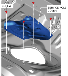
6.Disconnect the following parts:
-
• Fuel pump unit connector• Quick release connector (See QUICK RELEASE CONNECTOR (FUEL SYSTEM) REMOVAL/INSTALLATION [SKYACTIV-G (WITHOUT CYLINDER DEACTIVATION (US))].)
7.Remove the floor under cover No.1 (LH). (See FLOOR UNDER COVER REMOVAL/INSTALLATION.)
8.Remove the floor under cover No.2. (See FLOOR UNDER COVER REMOVAL/INSTALLATION .)
9.Remove the TWC and HO2S as a single unit. (See EXHAUST SYSTEM REMOVAL/INSTALLATION [SKYACTIV-G (WITH CYLINDER DEACTIVATION (US))].)
10.Remove the insulator (middle). (See EXHAUST SYSTEM REMOVAL/INSTALLATION [SKYACTIV-G (WITH CYLINDER DEACTIVATION (US))].)
11.Remove in the order indicated in the table.
12.Install in the reverse order of removal.
13.Complete the “AFTER SERVICE PRECAUTION”. (See AFTER SERVICE PRECAUTION [SKYACTIV-G (WITHOUT CYLINDER DEACTIVATION (US))].)
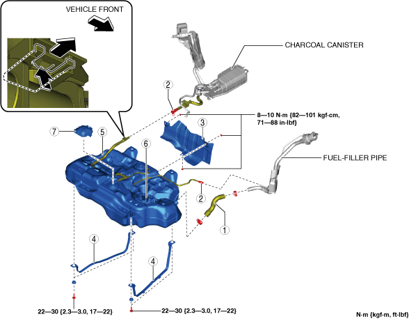
U.S.A. and CANADA
am3zzw00029127
|
|
1
|
Joint hose
(See Joint Hose Installation Note.)
|
|
2
|
Quick release connector
|
|
3
|
Fuel tank insulator
|
|
4
|
Fuel tank strap
|
|
5
|
Fuel tank
(See Fuel Tank Removal Note.)
|
|
6
|
Fuel pump unit
|
|
7
|
Cover
|
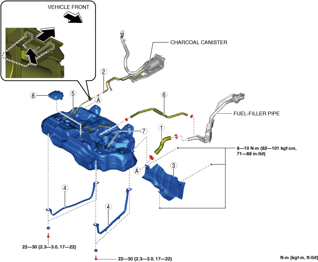
Except U.S.A. and CANADA
am3zzw00029128
|
|
1
|
Joint hose
(See Joint Hose Installation Note.)
|
|
2
|
Evaporative hose
|
|
3
|
Fuel tank insulator
|
|
4
|
Fuel tank strap
|
|
5
|
Fuel tank
(See Fuel Tank Removal Note.)
|
|
6
|
Breather hose
|
|
7
|
Fuel pump unit
|
|
8
|
Cover
|
Fuel Tank Removal Note
U.S.A. and CANADA
1.Remove the following parts as single unit:
-
• Fuel pump unit• Fuel tank• Cover
2.Remove the fuel tank.
Except U.S.A. and CANADA
1.Disconnect the breather hose from the fuel-filler pipe side.
2.Remove the following parts as single unit:
-
• Breather hose• Fuel pump unit• Fuel tank• Cover
3.Remove the fuel tank.
Evaporative Hose Installation Note
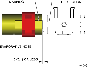
1.Align the evaporative hose marking with the projection on the pipe as shown in the figure and assemble.
am3zzw00029126
|
Breather Hose Installation Note
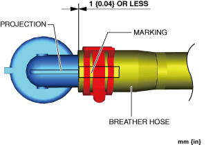
1.Align the breather hose marking with the projection on the pipe as shown in the figure and assemble.
Fuel tank side
am3zzw00021225
|
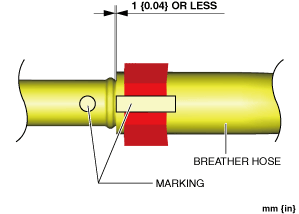
2.Align the breather hose marking with the fuel-filler pipe marking as shown in the figure and assemble.
Fuel-filler pipe side
am3zzw00021191
|
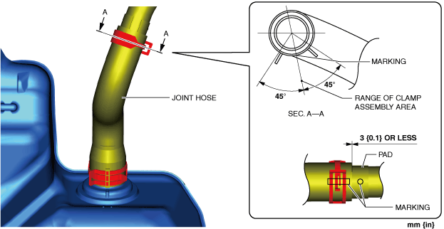
Joint Hose Installation Note
1.Align the joint hose marking with the pipe marking as shown in the figure and assemble.
Fuel tank side
am3zzw00022971
|
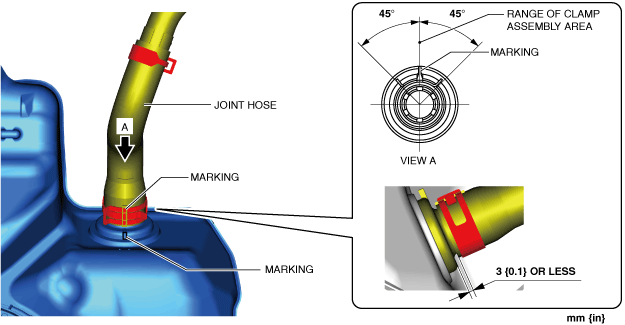
2.Align the joint hose marking with the fuel-filler pipe marking as shown in the figure and assemble.
Fuel-filler pipe side
am3zzw00028584
|