DTC P0011:00 OR P0012:00 [PCM (SKYACTIV-G)]
DTC P0011:00 OR P0012:00 [PCM (SKYACTIV-G)]
SM2334476
id0102t4400000
-
Note
-
• To determine the malfunctioning part, proceed with the diagnostics from “Function Inspection Using M-MDS”.
Details On DTCs
|
Description |
Electric variable valve timing control system: • P0011:00: Over-advanced
• P0012:00: Over-retarded
|
||
|---|---|---|---|
|
Detection condition
|
Determination conditions
|
• P0011:00: For the advance amount from the maximum intake valve retard position, a condition in which the actual advance amount is larger than the target value continues for a specified period of time.
|
|
|
• P0012:00: For the advance amount from the maximum intake valve retard position, a condition in which the actual advance amount is smaller than the target value continues for a specified period of time.
|
|||
|
Preconditions
|
• Battery voltage: above 11 V *1
• Engine speed: 5,000 rpm or less*1
• Engine coolant temperature: 20 °C {68 °F} or more *1
• The following DTCs are not detected:
*1: Standard can be verified by displaying PIDs using M-MDS
|
||
|
Malfunction determination period
|
• 10 s period
|
||
|
Drive cycle
|
• 1
|
||
|
Self test type
|
• CMDTC self test
|
||
|
Sensor used
|
• CKP sensor
• Intake CMP sensor
|
||
|
Fail-safe function
|
• Not applicable
|
||
|
Vehicle status when DTCs are output
|
• Not applicable
|
||
|
Possible cause
|
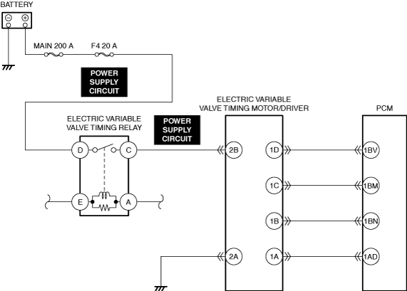
• Electric variable valve timing motor/driver connectors or terminals malfunction
• Short to ground or open circuit in electric variable valve timing relay power supply circuit
• Short to ground in electric variable valve timing motor/driver power supply circuit
• Open circuit in electric variable valve timing motor/driver power supply circuit
• PCM connector or terminals malfunction
• Electric variable valve timing relay malfunction
• Electric variable valve timing motor malfunction
• Electric variable valve timing actuator malfunction
• Timing chain malfunction
• Mis-detection of intake CMP sensor
• Mis-detection of CKP sensor
• PCM malfunction
|
||
 |
|||
 |
 |
||
 |
|||
 |
|||
Function Explanation (DTC Detection Outline)
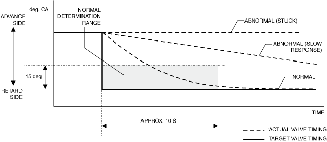
P0011:00
• With the preconditions met, the PCM verifies the conformity of the actual timing relative to the target valve timing. If it does not conform to the normal determination range (difference between target valve timing and actual valve timing is 15 degrees or less) during the malfunction determination period ( approx. 10 s), even if the target valve timing is set to the retard side, the PCM determines an excess advance malfunction condition and stores a DTC.
am3zzw00033536
|
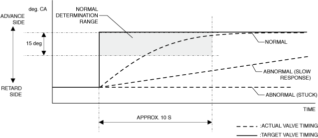
P0012:00
• With the preconditions met, the PCM verifies the conformity of the actual timing relative to the target valve timing. If it does not conform to the normal determination range (difference between target valve timing and actual valve timing is 15 degrees or less) during the malfunction determination period ( approx. 10 s), even if the target valve timing is set to the advance side, the PCM determines an excess retard malfunction condition and stores a DTC.
am3zzw00033537
|
Repeatability Verification Procedure
1. Warm up the engine to allow the engine coolant temperature to reach 80 °C {176 °F} or more.
-
Note
-
• Match the engine coolant temperature in the recorded freeze frame data/snapshot data, the vehicle speed, and engine speed values to the best extent possible while driving the vehicle.
2. Try to reproduce the malfunction by driving the vehicle for 5 min based on the values in the freeze frame data/snapshot data.
PID Item/Simulation Item Used In Diagnosis
PID/DATA monitor item table
|
PIDs |
Reference |
|---|---|
|
VLV_TIMING_ACT_IN
|
|
|
VLV_TIMING_DSD_IN
|
Function Inspection Using M-MDS
|
Step |
Inspection |
Results |
Action |
|---|---|---|---|
|
1
|
PURPOSE: VERIFY RELATED REPAIR INFORMATION OR SERVICE INFORMATION AVAILABILITY
• Verify related Service Bulletins, on-line repair information, or Service Information availability.
• Is any related Information available?
|
Yes
|
Perform repair or diagnosis according to the available information.
• If the vehicle is not repaired, go to the next step.
|
|
No
|
Go to the next step.
|
||
|
2
|
PURPOSE: RECORD VEHICLE STATUS WHEN DTC WAS DETECTED TO UTILIZE WITH REPEATABILITY VERIFICATION
• Record the freeze frame data/snapshot data.
|
—
|
Go to the next step.
|
|
3
|
PURPOSE: INSPECT FOR OTHER RELATED DTCs
• Perform the DTC inspection for the PCM. (See DTC INSPECTION.)
• Are any of the following DTCs displayed?
|
Yes
|
Repair the malfunctioning location according to the applicable DTC troubleshooting.
|
|
No
|
Go to the next step.
|
||
|
4
|
PURPOSE: VERIFY CONFORMITY OF ACTUAL INTAKE VALVE TIMING
• Start the engine and idle it.
• Access the following PIDs using the M-MDS: (See PID/DATA MONITOR INSPECTION.)
• Perform the following:
• Does the monitor value of the PID item VLV_TIMING_ACT_IN conform to the VLV_TIMING_DSD_IN PID value?
|
Yes
|
Go to the next step.
|
|
No
|
Go to Troubleshooting Diagnostic Procedure to perform the procedure from Step 1.
|
||
|
5
|
PURPOSE: VERIFY CONNECTOR CONNECTIONS
• Start the engine.
• Access the VLV_TIMING_ACT_IN PID using the M-MDS. (See PID/DATA MONITOR INSPECTION.)
• Does the PID value fluctuate when the following connectors are shaken?
|
Yes
|
Repair or replace the applicable wiring harness or connector parts.
Go to Troubleshooting Diagnostic Procedure to perform the repair completion verification.
|
|
No
|
Go to Troubleshooting Diagnostic Procedure to perform the procedure from Step 1.
|
Troubleshooting Diagnostic Procedure
Intention of troubleshooting procedure
• Step 1—5
-
― Perform an inspection of the connectors and wiring harnesses between the battery positive terminal and electric variable valve timing relay and the electric variable valve timing motor/driver.
• Step 6
-
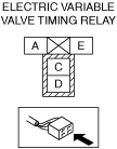
― Perform a unit inspection of the electric variable valve timing relay.
• Step 7—9
-
― Perform an inspection of the electric variable valve timing drive parts.
• Step 10—11
-
― Inspect the intake CMP sensor and CKP sensor detection areas for adhesion of foreign matter.
• Repair completion verification
-
― Verify that the primary malfunction is resolved and there are no other malfunctions.
|
Step |
Inspection |
Results |
Action |
|---|---|---|---|
|
1
|
PURPOSE: INSPECT ELECTRIC VARIABLE VALVE TIMING RELAY POWER SUPPLY CIRCUIT FOR SHORT TO GROUND AND OPEN CIRCUIT
• Inspect the power supply circuit for an open circuit and short to ground. (See CIRCUIT INSPECTION.)
• Is the circuit normal?
|
Yes
|
Go to the next step.
|
|
No
|
Repair or replace the malfunctioning location and perform the repair completion verification.
|
||
|
2
|
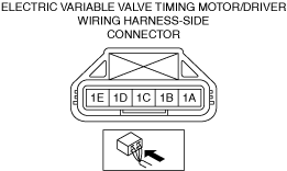
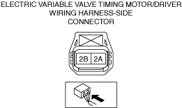
PURPOSE: INSPECT ELECTRIC VARIABLE VALVE TIMING MOTOR/DRIVER CONNECTOR FOR MALFUNCTION
• Inspect the applicable connector and terminal. (See CONNECTOR INSPECTION.)
• Are the connector and terminal normal?
|
Yes
|
Go to the next step.
|
|
No
|
Repair or replace the malfunctioning location and perform the repair completion verification.
|
||
|
3
|
PURPOSE: INSPECT ELECTRIC VARIABLE VALVE TIMING MOTOR/DRIVER POWER SUPPLY CIRCUIT FOR SHORT TO GROUND
• Inspect the applicable circuit for a short to ground. (See CIRCUIT INSPECTION.)
• Is the circuit normal?
|
Yes
|
Go to the next step.
|
|
No
|
Repair or replace the malfunctioning location and perform the repair completion verification.
|
||
|
4
|
PURPOSE: INSPECT ELECTRIC VARIABLE VALVE TIMING MOTOR/DRIVER POWER SUPPLY CIRCUIT FOR OPEN CIRCUIT
• Inspect the applicable circuit for open circuit. (See CIRCUIT INSPECTION.)
• Is the circuit normal?
|
Yes
|
Go to the next step.
|
|
No
|
Repair or replace the malfunctioning location and perform the repair completion verification.
|
||
|
5
|
PURPOSE: INSPECT PCM CONNECTOR FOR MALFUNCTION
• Inspect the applicable connector and terminal. (See CONNECTOR INSPECTION.)
• Are the connector and terminal normal?
|
Yes
|
Go to the next step.
|
|
No
|
Repair or replace the malfunctioning location and perform the repair completion verification.
|
||
|
6
|
PURPOSE: INSPECT ELECTRIC VARIABLE VALVE TIMING RELAY FOR MALFUNCTION
• Inspect the applicable part. (See RELAY INSPECTION.)
• Is the part normal?
|
Yes
|
Go to the next step.
|
|
No
|
Repair or replace the malfunctioning location and perform the repair completion verification.
(See RELAY LOCATION [(US)].)
|
||
|
7
|
PURPOSE: INSPECT ELECTRIC VARIABLE VALVE TIMING MOTOR FOR MALFUNCTION
• Inspect the applicable part. (See ELECTRIC VARIABLE VALVE TIMING MOTOR/DRIVER INSPECTION [SKYACTIV-G (WITH CYLINDER DEACTIVATION (US))].) (See ELECTRIC VARIABLE VALVE TIMING MOTOR/DRIVER INSPECTION [SKYACTIV-G (WITHOUT CYLINDER DEACTIVATION (US))].)
• Is the part normal?
|
Yes
|
Go to the next step.
|
|
No
|
Repair or replace the malfunctioning location and perform the repair completion verification.
|
||
|
8
|
PURPOSE: INSPECT ELECTRIC VARIABLE VALVE TIMING ACTUATOR FOR MALFUNCTION
• Inspect the applicable part. (See ELECTRIC VARIABLE VALVE TIMING MOTOR/DRIVER INSPECTION [SKYACTIV-G (WITH CYLINDER DEACTIVATION (US))].) (See ELECTRIC VARIABLE VALVE TIMING MOTOR/DRIVER INSPECTION [SKYACTIV-G (WITHOUT CYLINDER DEACTIVATION (US))].)
• Is the part normal?
|
Yes
|
Go to the next step.
|
|
No
|
Repair or replace the malfunctioning location and perform the repair completion verification.
|
||
|
9
|
PURPOSE: VERIFY ASSEMBLY CONDITION OF TIMING CHAIN
• Verify the condition of the timing chain assembly (intake valve timing, looseness, jumping). (See TIMING CHAIN REMOVAL/INSTALLATION [SKYACTIV-G (WITH CYLINDER DEACTIVATION (US))].) (See TIMING CHAIN REMOVAL/INSTALLATION [SKYACTIV-G (WITHOUT CYLINDER DEACTIVATION (US))].)
• Is there any malfunction?
|
Yes
|
Repair or replace the malfunctioning part.
Assemble the timing chain using the correct timing.
Go to repair completion verification.
|
|
No
|
Go to the next step.
|
||
|
10
|
PURPOSE: VERIFY IF FOREIGN MATTER ON INTAKE CMP SENSOR DETECTION AREA AFFECTS DIAGNOSTIC RESULTS
• Visually inspect for intake CMP sensor. (See CAMSHAFT POSITION (CMP) SENSOR INSPECTION [SKYACTIV-G (WITH CYLINDER DEACTIVATION (US))].) (See CAMSHAFT POSITION (CMP) SENSOR INSPECTION [SKYACTIV-G (WITHOUT CYLINDER DEACTIVATION (US))].)
• Is there foreign matter such as metallic dust on the intake CMP sensor detection area?
|
Yes
|
Remove the foreign matter and perform the repair completion verification.
|
|
No
|
Go to the next step.
|
||
|
11
|
PURPOSE: VERIFY IF FOREIGN MATTER ON CKP SENSOR DETECTION AREA AFFECTS DIAGNOSTIC RESULTS
• Visually inspect for CKP sensor. (See CRANKSHAFT POSITION (CKP) SENSOR INSPECTION [SKYACTIV-G (WITH CYLINDER DEACTIVATION (US))].) (See CRANKSHAFT POSITION (CKP) SENSOR INSPECTION [SKYACTIV-G (WITHOUT CYLINDER DEACTIVATION (US))].)
• Is there foreign matter such as metallic dust on the CKP sensor detection area?
|
Yes
|
Remove the foreign matter and perform the repair completion verification.
|
|
No
|
Go to the next step.
|
||
|
Repair completion verification 1
|
PURPOSE: VERIFY THAT VEHICLE IS REPAIRED
• Install/connect the part removed/disconnected during the troubleshooting procedure.
• Clear the DTC recorded in the memory. (See CLEARING DTC.)
• Replicate the vehicle conditions at the time the DTC was detected using the following procedure.
• Perform the DTC inspection for the PCM. (See DTC INSPECTION.)
• Is the same Pending DTC present?
|
Yes
|
Refer to the controller area network (CAN) malfunction diagnosis flow to inspect for a CAN communication error.
If the CAN communication is normal, perform the diagnosis from Step 1.
• If the malfunction recurs, replace the PCM, then go to the next step. (See PCM REMOVAL/INSTALLATION [SKYACTIV-G (WITH CYLINDER DEACTIVATION (US))].) (See PCM REMOVAL/INSTALLATION [SKYACTIV-G (WITHOUT CYLINDER DEACTIVATION (US))].)
|
|
No
|
Go to the next step.
|
||
|
Repair completion verification 2
|
PURPOSE: VERIFY IF OTHER DTCs DISPLAYED
• Perform the DTC inspection. (See DTC INSPECTION.)
• Are any other DTCs displayed?
|
Yes
|
Repair the malfunctioning location according to the applicable DTC troubleshooting.
|
|
No
|
DTC troubleshooting completed.
|