CAMSHAFT POSITION (CMP) SENSOR INSPECTION [SKYACTIV-G (WITHOUT CYLINDER DEACTIVATION (US))]
CAMSHAFT POSITION (CMP) SENSOR INSPECTION [SKYACTIV-G (WITHOUT CYLINDER DEACTIVATION (US))]
SM2565859
id0140u0801400
-
Caution
-
• When replacing the CMP sensor, make sure there is no foreign matter on it such as metal shavings. If it is installed with foreign matter, the sensor output signal will malfunction resulting from fluctuation in magnetic flux and cause a deterioration in engine control.• If the wiring harnesses or waterproof connectors are damaged, water penetrating the connector will cause a sensor malfunction. To prevent this, be careful not to damage wiring harnesses or waterproof connectors.
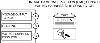
Intake CMP Sensor
Visual inspection
1.Disconnect the negative battery terminal. (See NEGATIVE BATTERY TERMINAL DISCONNECTION/CONNECTION [(US)].)
2.Remove the intake CMP sensor. (See CAMSHAFT POSITION (CMP) SENSOR REMOVAL/INSTALLATION [SKYACTIV-G (WITHOUT CYLINDER DEACTIVATION (US))].)
3.Verify that there are no metal shavings on the intake CMP sensor.
-
• If there is a malfunction, remove any metal shavings that are adhering.
Voltage inspection
1.Idle the engine.
2.Measure the output voltage wave pattern between intake CMP sensor terminals A and B using an oscilloscope.
-
• If not as specified, replace the intake CMP sensor. (See CAMSHAFT POSITION (CMP) SENSOR REMOVAL/INSTALLATION [SKYACTIV-G (WITHOUT CYLINDER DEACTIVATION (US))].)
am3zzw00034823
|
-
• Specification
-
4.8 V or more (Maximum value of wave pattern)0.8 V or less (Minimum value of wave pattern)
-
Wave pattern (reference)
adejjw00007911
|
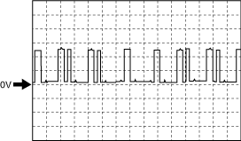
- Oscilloscope setting
-
• 2 V/DIV (Y), 20 ms/DIV (X), DC range
- Vehicle condition
-
• Idle (after warm up)
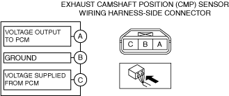
Exhaust CMP Sensor
Visual inspection
1.Disconnect the negative battery terminal. (See NEGATIVE BATTERY TERMINAL DISCONNECTION/CONNECTION [(US)].)
2.Remove the exhaust CMP sensor. (See CAMSHAFT POSITION (CMP) SENSOR REMOVAL/INSTALLATION [SKYACTIV-G (WITHOUT CYLINDER DEACTIVATION (US))].)
3.Verify that there are no metal shavings on the exhaust CMP sensor.
-
• If there is a malfunction, remove any metal shavings that are adhering.
Voltage inspection
1.Idle the engine.
2.Measure the output voltage wave pattern between exhaust CMP sensor terminals A and B using an oscilloscope.
-
• If not as specified, replace the exhaust CMP sensor. (See CAMSHAFT POSITION (CMP) SENSOR REMOVAL/INSTALLATION [SKYACTIV-G (WITHOUT CYLINDER DEACTIVATION (US))].)
am3zzw00034824
|
-
• Specification
-
4.8 V or more (Maximum value of wave pattern)0.8 V or less (Minimum value of wave pattern)
-
Wave pattern (reference)
adejjw00007911
|
- Oscilloscope setting
-
• 2 V/DIV (Y), 20 ms/DIV (X), DC range
- Vehicle condition
-
• Idle (after warm up)