ELECTRIC PARKING BRAKE AUTOMATIC RELEASE FUNCTION DURING ACCELERATION DOES NOT OPERATE [ELECTRIC PARKING BRAKE (US)]
ELECTRIC PARKING BRAKE AUTOMATIC RELEASE FUNCTION DURING ACCELERATION DOES NOT OPERATE [ELECTRIC PARKING BRAKE (US)]
SM2565949
id040328250534
|
Troubleshooting item |
Electric parking brake automatic release function during acceleration does not operate |
|
|---|---|---|
|
Description
|
• Electric parking brake automatic release function during acceleration does not operate.
|
|
|
Possible cause
|
• DSC HU/CM malfunction
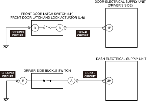
• Front door latch and lock actuator (LH) connector or terminal malfunction
• Front door latch switch (LH) malfunction
• Door-electrical supply unit, driver connector or terminal malfunction
• Short to ground in front door latch switch (LH) signal circuit
• Door-electrical supply unit, driver malfunction
• Driver-side buckle switch connector or terminal malfunction
• Driver-side buckle switch malfunction
• Dash-electrical supply unit connector or terminal malfunction
• Short to ground in driver-side buckle switch signal circuit
• Dash-electrical supply unit malfunction
|
|
 |
||
 |
 |
|
 |
 |
|
Diagnostic Procedure
|
Step |
Inspection |
Results |
Action |
|---|---|---|---|
|
1
|
VERIFY ALL SYSTEM DTCs
• Switch the ignition off.
• Switch the ignition ON (engine off or on) and wait for 10 s or more.
• Perform a DTC inspection using the M-MDS. (See DTC INSPECTION.)
• Are any DTCs displayed?
|
Yes
|
Repair or replace the malfunctioning part according to the applicable DTC troubleshooting.
(See DTC TABLE [DSC HU/CM (US)].)
|
|
No
|
Go to the next step.
|
||
|
2
|
VERIFY IF THE ELECTRIC PARKING BRAKE WARNING LIGHT IS TURNED ON
• Verify if the electric parking brake warning light is turned on.
• Is the electric parking brake warning light turned on?
|
Yes
|
Perform an inspection referring to “ELECTRIC PARKING BRAKE WARNING LIGHT TURNS ON”.
|
|
No
|
Go to the next step.
|
||
|
3
|
DETERMINE MALFUNCTIONING LOCATION BY PERFORMING PID/DATA MONITOR INSPECTION
• Using the M-MDS, display the following PIDs for the door-electrical supply unit, driver. (See PID/DATA MONITOR INSPECTION.)
• Using the M-MDS, display the following PIDs for the dash-electrical supply unit. (See PID/DATA MONITOR INSPECTION.)
• Does the PID monitoring value switch correctly in conjunction with the opening/closing of the front door (LH) or with the driver’s seat belt fastened?
|
Yes
|
Replace the DSC HU/CM, and perform the repair completion verification.
|
|
No
|
Not in conjunction with front door (LH) open/close
• Go to the next step.
Not in conjunction with driver’s seat belt fastened
• Go to Step 8.
|
||
|
4
|
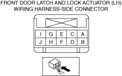
INSPECT FRONT DOOR LATCH AND LOCK ACTUATOR (LH) CONNECTOR CONDITION
• Switch the ignition off.
• Disconnect the negative battery terminal. (See NEGATIVE BATTERY TERMINAL DISCONNECTION/CONNECTION [(US)].)
• Disconnect the front door latch and lock actuator (LH) connector.
• Inspect the connector engagement and connection condition and inspect the terminals for damage, deformation, corrosion, or disconnection.
• Is the connector normal?
|
Yes
|
Go to the next step.
|
|
No
|
Repair or replace the connector, and perform the repair completion verification.
|
||
|
5
|
INSPECT FRONT DOOR LATCH SWITCH (LH)
• Inspect the front door latch switch (LH). (See FRONT DOOR LATCH AND LOCK ACTUATOR INSPECTION [(US)].)
• Is the front door latch switch (LH) normal?
|
Yes
|
Go to the next step.
|
|
No
|
Replace the front door latch and lock actuator (LH), and perform the repair completion verification.
|
||
|
6
|
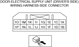
INSPECT DOOR-ELECTRICAL SUPPLY UNIT,DRIVER CONNECTOR CONDITION
• Disconnect the door-electrical supply unit, driver connector.
• Inspect the connector engagement and connection condition and inspect the terminals for damage, deformation, corrosion, or disconnection.
• Is the connector normal?
|
Yes
|
Go to the next step.
|
|
No
|
Repair or replace the connector, and perform the repair completion verification.
|
||
|
7
|
INSPECT FRONT DOOR LATCH SWITCH (LH) SIGNAL CIRCUIT FOR SHORT TO GROUND
• Inspect the signal circuit for a short to ground. (See CIRCUIT INSPECTION.)
• Is the circuit normal?
|
Yes
|
Replace the door-electrical supply unit, and perform the repair completion verification.
|
|
No
|
Repair or replace the malfunctioning location.
|
||
|
8
|
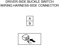
INSPECT DRIVER-SIDE BUCKLE SWITCH CONNECTOR CONDITION
• Switch the ignition off.
• Disconnect the negative battery terminal. (See NEGATIVE BATTERY TERMINAL DISCONNECTION/CONNECTION [(US)].)
• Disconnect the driver-side buckle switch connector.
• Inspect the connector engagement and connection condition and inspect the terminals for damage, deformation, corrosion, or disconnection.
• Is the connector normal?
|
Yes
|
Go to the next step.
|
|
No
|
Repair or replace the connector, and perform the repair completion verification.
|
||
|
9
|
INSPECT DRIVER-SIDE BUCKLE SWITCH
• Inspect the driver-side buckle switch. (See BUCKLE SWITCH INSPECTION [(US)].)
• Is the driver-side buckle switch normal?
|
Yes
|
Go to the next step.
|
|
No
|
Replace the driver-side front buckle, and perform the repair completion verification.
|
||
|
10
|
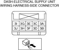
INSPECT DASH-ELECTRICAL SUPPLY UNIT CONNECTOR CONDITION
• Disconnect the dash-electrical supply unit connector.
• Inspect the connector engagement and connection condition and inspect the terminals for damage, deformation, corrosion, or disconnection.
• Is the connector normal?
|
Yes
|
Go to the next step.
|
|
No
|
Repair or replace the connector, and perform the repair completion verification.
|
||
|
11
|
INSPECT DRIVER-SIDE BUCKLE SWITCH SIGNAL CIRCUIT FOR SHORT TO GROUND
• Inspect the signal circuit for a short to ground. (See CIRCUIT INSPECTION.)
• Is the circuit normal?
|
Yes
|
Replace the dash-electrical supply unit, and perform the repair completion verification.
|
|
No
|
Repair or replace the malfunctioning location, and perform the repair completion verification.
|
||
|
Repair completion verification
|
VERIFY THAT MALFUNCTION SYMPTOMS DO NOT RECUR AFTER REPAIR
• Install/connect the part removed/disconnected during the troubleshooting procedure.
• Has the malfunction symptom been eliminated?
|
Yes
|
Complete the symptom troubleshooting.
Explain to the customer what has been repaired.
|
|
No
|
Refer to the controller area network (CAN) malfunction diagnosis flow to inspect for a CAN communication error.
If the CAN communication is normal, perform the diagnosis from Step 1.
|