DOOR-ELECTRICAL SUPPLY UNIT REMOVAL/INSTALLATION
DOOR-ELECTRICAL SUPPLY UNIT REMOVAL/INSTALLATION
SM2336733
id094000004400
-
Caution
-
• When replacing the door-electrical supply unit (ESU), perform the configuration to assure that the system operates correctly. (See CONFIGURATION.)
Driver’s Side
1.Disconnect the negative battery terminal. (See NEGATIVE BATTERY TERMINAL DISCONNECTION/CONNECTION [(US)].)
2.Remove the following parts:
- (1)Front door speaker grille (See SPEAKER GRILLE REMOVAL/INSTALLATION.)
- (2)Inner garnish (See INNER GARNISH REMOVAL/INSTALLATION.)
- (3)Power window main switch (See POWER WINDOW MAIN SWITCH REMOVAL/INSTALLATION.)
- (4)Front door trim (See FRONT DOOR TRIM REMOVAL/INSTALLATION [(US)].)
3.Disconnect the connectors.
am3zzw00022228
|
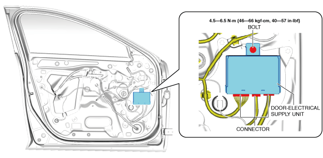
4.Remove the bolt.
5.Lift up the door-electrical supply unit in the direction of the arrow shown in the figure and pull out the hooks from the service hole cover.
am3zzw00028097
|
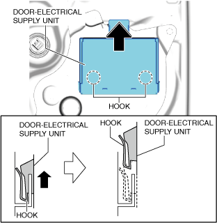
6.Remove the door-electrical supply unit.
7.Install in the reverse order of removal.
8.If the door-electrical supply unit (driver’s side) is replaced, perform the following procedure:
- (1)Complete the door-electrical supply unit (driver’s side) automatic configuration using the following procedure.
-
- 1)Switch the ignition ON (engine off or on).
- 2)Switch the ignition OFF.
- 3)Switch the ignition ON (engine off or on) again.
- (2)Clear the position memory system memory using the M-MDS. (With position memory system) (See POSITION MEMORY SYSTEM MEMORY CLEARING.)
- (3)Synchronize the door-electrical supply unit (driver’s side) with the electrical supply unit (ESU), the door-electrical supply unit (passenger’s side), and the body control module (BCM), using the following procedure.
-
- 1)Switch the ignition ON (engine off or on) and wait for 1 s or more.
- 2)Switch the ignition OFF.
- (4)Perform the power window system initial setting. (See POWER WINDOW SYSTEM INITIALIZATION PROCEDURE.)
- (5)Clear the DTC. (See CLEARING DTC.)
Passenger’s Side
1.Disconnect the negative battery terminal. (See NEGATIVE BATTERY TERMINAL DISCONNECTION/CONNECTION [(US)].)
2.Remove the following parts:
- (1)Front door speaker grille (See SPEAKER GRILLE REMOVAL/INSTALLATION.)
- (2)Inner garnish (See INNER GARNISH REMOVAL/INSTALLATION.)
- (3)Power window subswitch (See POWER WINDOW SUBSWITCH REMOVAL/INSTALLATION.)
- (4)Front door trim (See FRONT DOOR TRIM REMOVAL/INSTALLATION [(US)].)
3.Disconnect the connectors.
am3zzw00022230
|

4.Remove the bolt.
5.Lift up the door-electrical supply unit in the direction of the arrow shown in the figure and pull out the hooks from the service hole cover.
am3zzw00028098
|
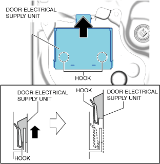
6.Remove the door-electrical supply unit.
7.Install in the reverse order of removal.
8.If the door-electrical supply unit (passenger’s side) is replaced, perform the following procedure:
- (1)Complete the door-electrical supply unit (passenger’s side) automatic configuration using the following procedure.
-
- 1)Switch the ignition ON (engine off or on).
- 2)Switch the ignition OFF.
- 3)Switch the ignition ON (engine off or on) again.
- (2)Clear the position memory system memory using the M-MDS. (With position memory system) (See POSITION MEMORY SYSTEM MEMORY CLEARING.)
- (3)Synchronize the door-electrical supply unit (passenger’s side) with the electrical supply unit (ESU), the door-electrical supply unit (driver’s side), and the body control module (BCM), using the following procedure.
-
- 1)Switch the ignition ON (engine off or on) and wait for 1 s or more.
- 2)Switch the ignition OFF.
- (4)Perform the power window system initial setting. (See POWER WINDOW SYSTEM INITIALIZATION PROCEDURE.)
- (5)Clear the DTC. (See CLEARING DTC.)