DSC HU/CM REMOVAL/INSTALLATION [L.H.D. (US)]
DSC HU/CM REMOVAL/INSTALLATION [L.H.D. (US)]
SM2565976
id0415008010x5
Oil and Chemical Type
|
Brake fluid type
Type: SAE J1703 or FMVSS116 DOT-3
|
-
Caution
-
• When replacing the DSC HU/CM, perform the configuration to assure that the system operates correctly. (See CONFIGURATION.)• The internal parts of the DSC HU/CM could be damaged if dropped. Be careful not to drop the DSC HU/CM. Replace the DSC HU/CM if it is subjected to an impact.• Brake fluid will damage painted surfaces. Be careful not to spill any on painted surfaces. In addition, if there is any brake fluid on the wiring harness, the wire insulation may corrode causing a malfunction such as a short circuit. If brake fluid gets on a painted surface or wiring harness, wash and flush it off completely with water immediately.
-
Note
-
• The DSC HU/CM records the vehicle specification information and the electric parking brake operation/release condition.• Tighten the brake pipe flare nut using any commercially available flare nut wrench.
1.Disconnect the negative battery terminal. (See NEGATIVE BATTERY TERMINAL DISCONNECTION/CONNECTION [(US)].)
2.Remove the following parts:
- (1)Windshield wiper arm and blade (See WINDSHIELD WIPER ARM AND BLADE REMOVAL/INSTALLATION.)
- (2)Cowl grille (See COWL GRILLE REMOVAL/INSTALLATION.)
- (3)Windshield wiper motor and link (See WINDSHIELD WIPER MOTOR AND LINK REMOVAL/INSTALLATION.)
- (4)Side cowl grille (See COWL GRILLE REMOVAL/INSTALLATION.)
- (5)Cowl panel (See COWL PANEL REMOVAL/INSTALLATION [(US)].)
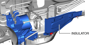
3.Remove the insulator. (See EXHAUST SYSTEM REMOVAL/INSTALLATION [SKYACTIV-G (WITH CYLINDER DEACTIVATION (US))].) (See EXHAUST SYSTEM REMOVAL/INSTALLATION [SKYACTIV-G (WITH CYLINDER DEACTIVATION (US))].)
am3zzw00025091
|
4.Remove in the order indicated in the table.
5.Install in the reverse order of removal.
6.After installation, add brake fluid, bleed the air, and inspect for fluid leakage. (See BRAKE FLUID AIR BLEEDING [(US)].)
7.If the DSC HU/CM is replaced, perform the following procedure.
- (1)Perform manual configuration using the following procedure.
-
- 1)Connect the M-MDS to the DLC-2.
- 2)Switch the ignition ON (engine off or on).
- 3)Perform vehicle identification.
- 4)Select [Configuration] using the M-MDS.
- 5)Select [DSC].
- 6)Perform manual configuration following the instructions on the screen.
- (2)Switch the ignition OFF.
- (3)Complete the DSC HU/CM automatic configuration using the following procedure.
-
- 1)Switch the ignition ON (engine off or on) and wait for 10 s or more.
- 2)Switch the ignition OFF and wait for 3 s or more.
- 3)Switch the ignition ON (engine off or on) again and wait for 3 s or more.
- (4)Clear the DTC. (See CLEARING DTC.)
- (5)Perform the sensor initialization for the DSC-related parts. (See DSC RELATED PARTS SENSOR INITIALIZATION PROCEDURE [(US)].)
- (6)Check the related parts using the following procedure.
-
- 1)Operate the electric parking brake.
- 2)Release the electric parking brake.
- 3)Operate the electric parking brake.
- 4)Release the electric parking brake.
- (7)Clear the DTC. (See CLEARING DTC.)
- (8)Verify that the following warning/indicator lights turn off.
-
-
• Brake system warning light• ABS warning light• TCS/DSC indicator light• DSC OFF indicator light• Electric parking brake indicator light• Brake control system warning light
 am3zzw00035342• If the warning/indicator lights do not turn off, perform a DTC inspection. (See DTC INSPECTION.)
-

- (9)Operate the electric parking brake.
- (10)Verify that the electric parking brake indicator light turns on and the brake control system warning light turns off.
-
-
• If the electric parking brake indicator light does not turn on, the electric parking brake indicator light flashes, or the brake control system warning light does not turn off, perform a DTC inspection as a malfunction of the electric parking brake may have occurred. (See DTC INSPECTION.)
-
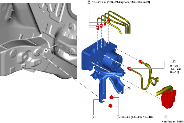
Step 1
am3zzw00025092
|
|
1
|
DSC HU/CM connector
|
|
2
|
Brake pipe
(See Brake Pipe Removal Note.)
(See Brake Pipe Installation Note.)
|
|
3
|
Nut
(See Nuts Installation Note.)
|
|
4
|
DSC HU/CM component
|
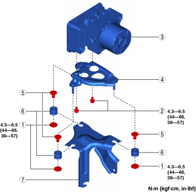
Step 2
am3zzw00025093
|
|
1
|
Nut
|
|
2
|
Bolt
|
|
3
|
DSC HU/CM
|
|
4
|
Bracket
|
|
5
|
Spacer
|
|
6
|
Mount rubber
|
|
7
|
Bracket
|
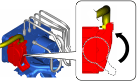
DSC HU/CM Connector Removal Note
-
Caution
-
• If sand or other particles get into the connector, it may be difficult to remove. To prevent damaging the connector, be careful not to use excessive force when disconnecting it.
1.Pull the lock lever down in the direction of the arrow while pressing the tab of the lock lever.
am3zzw00025094
|
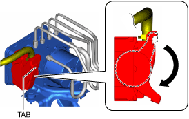
2.Disconnect the DSC HU/CM connector.
Brake Pipe Removal Note
1.Place an alignment mark on the brake pipe and DSC HU/CM.
am3zzw00025095
|
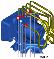
2.Apply protective tape to the connector to prevent brake fluid from entering.
3.Disconnect the brake pipes.
Nuts Installation Note
1.Tighten nut A to the specified torque.
am3zzw00025096
|
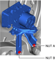
2.Tighten nut B to the specified torque.
Brake Pipe Installation Note
1.Align the marks made before removal and install the brake pipe to the DSC HU/CM and brake pipe joint referring to the figure.
am3zzw00025097
|
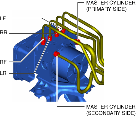
2.Tighten the brake pipe to the specified torque using the commercially available flare nut wrench.
DSC HU/CM Connector Installation Note
1.Connect the connector and pull the lock lever up in the direction of the arrow.
am3zzw00025098
|
2.After connecting the connector, verify that the connector cover is completely pushed in.