A/C DOES NOT WORK SUFFICIENTLY [SKYACTIV-G]
A/C DOES NOT WORK SUFFICIENTLY [SKYACTIV-G]
SM2334624
id0103s4891000
|
Troubleshooting item |
A/C does not work sufficiently |
|
|---|---|---|
|
Description
|
• A/C compressor magnetic clutch does not engage when A/C switch is turned on.
• Compressor valve inoperative
|
|
|
Possible cause
|
• PCM, body control module (BCM) or dash-electrical supply unit DTC is stored
• Refrigerant pressure sensor No.1 malfunction
• Refrigerant pressure sensor No.2 malfunction
• Improper refrigerant charging amount
• Seized A/C compressor
• Evaporator temperature sensor malfunction
• Short or open circuit in any of the following evaporator temperature sensor circuits.
• Body control module (BCM) malfunction (Does not receive A/C request signal from climate control unit or transmit it to PCM)
• Climate control unit malfunction (A/C switch malfunction or climate control unit does not determine A/C request or transmit A/C request signal)
• Open circuit in wiring harness between magnetic clutch and body ground
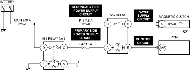
• A/C relay stuck open
• Compressor valve malfunction (built-into A/C compressor)
• Open circuit in A/C relay primary side power supply circuit
• Open circuit in A/C relay secondary side power supply circuit
• Open circuit in A/C relay control circuit
• Open circuit in magnetic clutch power supply circuit
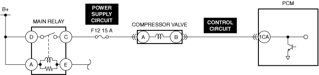
• Open circuit in compressor valve power supply circuit
• Open circuit in compressor valve control circuit
|
|
 |
||
 |
||
 |
||
 |
 |
|
 |
 |
|
 |
||
 |
 |
|
 |
||
 |
||
-
Caution
-
• Verify the malfunction symptom according to not only the PID value but also the symptom troubleshooting.
Related PIDs
|
PIDs |
Reference |
|---|---|
|
A/C_REQ
|
|
|
A/C_SW
|
Related Simulation items
|
Simulation items |
Reference |
|---|---|
|
A/C_SW
|
Diagnostic Procedure
|
Step |
Inspection |
Results |
Action |
|---|---|---|---|
|
1
|
VERIFY PCM DTC
• Perform the DTC inspection for the PCM. (See DTC INSPECTION.)
• Are any DTCs displayed?
|
Yes
|
Repair the malfunctioning location according to the applicable DTC troubleshooting.
|
|
No
|
Go to the next step.
|
||
|
2
|
VERIFY BODY CONTROL MODULE (BCM) DTC
• Perform the DTC inspection for the body control module (BCM). (See DTC INSPECTION.)
• Are any DTCs displayed?
|
Yes
|
Repair the malfunctioning location according to the applicable DTC troubleshooting.
|
|
No
|
Go to the next step.
|
||
|
3
|
VERIFY DASH-ELECTRICAL SUPPLY UNIT DTC
• Perform the DTC inspection for the dash-electrical supply unit. (See DTC INSPECTION.)
• Are any DTCs displayed?
|
Yes
|
Repair the malfunctioning location according to the applicable DTC troubleshooting.
|
|
No
|
Go to the next step.
|
||
|
4
|
DETERMINE IF MALFUNCTION CAUSE IS A/C RELAY CONTROL SIGNAL OR A/C REQUEST SIGNAL
• Access the PCM simulation item A/C_SW using the M-MDS. (See SIMULATION INSPECTION.)
• Start the engine and idle it.
• Turn the A/C_SW PID to ON from OFF using the M-MDS simulation function.
• Is the magnetic clutch engaged?
|
Yes
|
Go to the next step.
|
|
No
|
Go to Step 10.
|
||
|
5
|
DETERMINE IF MALFUNCTION CAUSE IS REFRIGERANT PRESSURE SENSOR OR OTHER
• Access the PCM PID A/C_REQ using the M-MDS. (See PID/DATA MONITOR INSPECTION.)
• Monitor the A/C_REQ PID while turning on and off the air conditioner using the switch on the control panel.
• Is the A/C_REQ PID value normal?
|
Yes
|
Go to the next step.
|
|
No
|
Go to Step 7.
|
||
|
6
|
INSPECT REFRIGERANT PRESSURE SENSOR No.1 AND No.2 FOR MALFUNCTION
• Inspect the applicable part. (See REFRIGERANT PRESSURE SENSOR INSPECTION [FULL-AUTO AIR CONDITIONER (US)].) (See REFRIGERANT PRESSURE SENSOR INSPECTION [MANUAL AIR CONDITIONER (US)].)
• Is the part normal?
|
Yes
|
Inspect the following:
• Refrigerant charging amount
• A/C compressor seized
|
|
No
|
Repair or replace the malfunctioning location and perform the repair completion verification.
|
||
|
7
|
DETERMINE IF MALFUNCTION CAUSE IS EVAPORATOR TEMPERATURE SENSOR OR OTHER
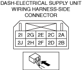
• Measure the voltage at the dash-electrical supply unit terminal 2E (wiring harness-side).
• Is the voltage normal? (See DASH-ELECTRICAL SUPPLY UNIT INSPECTION [FULL-AUTO AIR CONDITIONER (US)].) (See DASH-ELECTRICAL SUPPLY UNIT INSPECTION [MANUAL AIR CONDITIONER (US)].)
|
Yes
|
Go to Step 10.
|
|
No
|
Go to the next step.
|
||
|
8
|
INSPECT EVAPORATOR TEMPERATURE SENSOR FOR MALFUNCTION
• Inspect the applicable part. (See EVAPORATOR TEMPERATURE SENSOR INSPECTION [FULL-AUTO AIR CONDITIONER].) (See EVAPORATOR TEMPERATURE SENSOR INSPECTION [MANUAL AIR CONDITIONER].)
• Is the part normal?
|
Yes
|
Go to the next step.
|
|
No
|
Repair or replace the malfunctioning location and perform the repair completion verification.
|
||
|
9
|
INSPECT EVAPORATOR TEMPERATURE SENSOR SIGNAL CIRCUIT AND GROUND CIRCUIT FOR SHORT AND OPEN CIRCUIT
• Inspect the applicable circuit for short and open circuit. (See CIRCUIT INSPECTION.)
• Is the circuit normal?
|
Yes
|
Go to the next step.
|
|
No
|
Repair or replace the malfunctioning location and perform the repair completion verification.
|
||
|
10
|
DETERMINE IF MALFUNCTION CAUSE IS A/C CONTROL SIGNAL OR MAGNETIC CLUTCH
• Start the engine and idle it.
• Access the PCM simulation item A/C_SW using the M-MDS. (See SIMULATION INSPECTION.)
• Turn the A/C_SW PID to ON from OFF using the M-MDS simulation function.
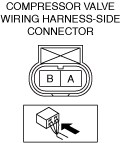
• Measure the voltage at the magnetic clutch terminal A (wiring harness-side).
• Is the voltage 10.5 V or more?
|
Yes
|
Go to the next step.
|
|
No
|
Go to Step 12.
|
||
|
11
|
INSPECT IF MALFUNCTION CAUSE IS MAGNETIC CLUTCH OR MAGNETIC CLUTCH GROUND CIRCUIT
• Switch the ignition off.
• Disconnect the magnetic clutch connector.
• Inspect for continuity between magnetic clutch terminal A (part-side) and body ground.
• Is there continuity?
|
Yes
|
Inspect the magnetic clutch.
Repair or replace the malfunctioning location and perform the repair completion verification.
|
|
No
|
Inspect the A/C compressor. (poor contact to ground)
• If there is any malfunction:
• If there is no malfunction:
|
||
|
12
|
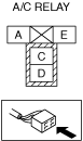
INSPECT A/C RELAY FOR MALFUNCTION
• Inspect the applicable part. (See RELAY INSPECTION.)
• Is the part normal?
|
Yes
|
Go to the next step.
|
|
No
|
Repair or replace the malfunctioning location and perform the repair completion verification.
(See RELAY LOCATION [(US)].)
|
||
|
13
|
INSPECT A/C RELAY PRIMARY SIDE POWER SUPPLY CIRCUIT FOR OPEN CIRCUIT
• Inspect the applicable circuit for open circuit. (See CIRCUIT INSPECTION.)
• Is the circuit normal?
|
Yes
|
Go to the next step.
|
|
No
|
Repair or replace the malfunctioning location and perform the repair completion verification.
|
||
|
14
|
INSPECT A/C RELAY SECONDARY SIDE POWER SUPPLY CIRCUIT FOR OPEN CIRCUIT
• Inspect the applicable circuit for open circuit. (See CIRCUIT INSPECTION.)
• Is the circuit normal?
|
Yes
|
Go to the next step.
|
|
No
|
Repair or replace the malfunctioning location and perform the repair completion verification.
|
||
|
15
|
INSPECT A/C RELAY CONTROL CIRCUIT FOR OPEN CIRCUIT
• Inspect the applicable circuit for open circuit. (See CIRCUIT INSPECTION.)
• Is the circuit normal?
|
Yes
|
Go to the next step.
|
|
No
|
Repair or replace the malfunctioning location and perform the repair completion verification.
|
||
|
16
|
INSPECT MAGNETIC CLUTCH POWER SUPPLY CIRCUIT FOR OPEN CIRCUIT
• Inspect the applicable circuit for open circuit. (See CIRCUIT INSPECTION.)
• Is the circuit normal?
|
Yes
|
Go to the next step.
|
|
No
|
Repair or replace the malfunctioning location and perform the repair completion verification.
|
||
|
17
|
INSPECT COMPRESSOR VALVE POWER SUPPLY CIRCUIT FOR OPEN CIRCUIT
• Inspect the applicable circuit for open circuit. (See CIRCUIT INSPECTION.)
• Is the circuit normal?
|
Yes
|
Go to the next step.
|
|
No
|
Repair or replace the malfunctioning location and perform the repair completion verification.
|
||
|
18
|
INSPECT COMPRESSOR VALVE CONTROL CIRCUIT FOR OPEN CIRCUIT
• Inspect the applicable circuit for open circuit. (See CIRCUIT INSPECTION.)
• Is the circuit normal?
|
Yes
|
Compressor valve can be considered the cause.
• Replace the A/C compressor and perform the repair completion verification. (See A/C COMPRESSOR REMOVAL/INSTALLATION [SKYACTIV-G 2.0, SKYACTIV-G 2.5].)
|
|
No
|
Repair or replace the malfunctioning location and perform the repair completion verification.
|
||
|
Repair completion verification 1
|
VERIFY THAT VEHICLE IS REPAIRED
• Install/connect the part removed/disconnected during the troubleshooting procedure.
• Has the malfunction symptom been eliminated?
|
Yes
|
Complete the symptom troubleshooting. (Explain contents of repair to customer)
|
|
No
|
Refer to the controller area network (CAN) malfunction diagnosis flow to inspect for a CAN communication error.
• If the CAN communication is normal, perform the diagnosis from Step 1.
|
||
|
Repair completion verification 2
|
VERIFY IF MALFUNCTION IS CAUSED BY NOT PERFORMING PCM REPROGRAMMING
• Verify repair information and verify that there is a new calibration in the PCM.
• Is there a new calibration in the PCM?
|
Yes
|
Perform the PCM reprogramming and verify if the malfunction symptom was corrected.
• If the malfunction recurs, replace the PCM. (See PCM REMOVAL/INSTALLATION [SKYACTIV-G (WITH CYLINDER DEACTIVATION (US))].) (See PCM REMOVAL/INSTALLATION [SKYACTIV-G (WITHOUT CYLINDER DEACTIVATION (US))].)
|
|
No
|
Replace the PCM.
|