DTC P2096:00 OR P2097:00 [PCM (SKYACTIV-G)]
DTC P2096:00 OR P2097:00 [PCM (SKYACTIV-G)]
SM2334488
id0102t4500300
-
Note
-
• To determine the malfunctioning part, proceed with the diagnostics from “Function Inspection Using M-MDS”.
Details On DTCs
|
Description |
HO2S fuel injection control system: • P2096:00: Air fuel too lean
• P2097:00: Air fuel too rich
|
|
|---|---|---|
|
Detection condition
|
Determination conditions
|
• P2096:00: Depending on the correction deviation of the A/F sensor, a condition in which the fuel feedback correction amount (SHRT_FUEL_TRIM_HO2S_SEN) for the HO2S is the specified value ( 2 %) or more and the sum (SHRT_FUEL_TRIM_HO2S_SEN+LONG_FUEL_TRIM_HO2S_SEN) of the fuel feedback correction amount and the fuel learning correction amount is the specified value ( 2.2 %) or more continues for a period of 25 s.
|
|
• P2097:00: Depending on the correction deviation of the A/F sensor, a condition in which the fuel feedback correction amount (SHRT_FUEL_TRIM_HO2S_SEN) for the HO2S is the specified value ( −2 %) or less and the sum (SHRT_FUEL_TRIM_HO2S_SEN+LONG_FUEL_TRIM_HO2S_SEN) of the fuel feedback correction amount and the fuel learning correction amount is the specified value ( −2.2 %) or less continues for a period of 25 s.
|
||
|
Preconditions
|
• HO2S estimated temperature: above 450 °C {842 °F}
|
|
|
Malfunction determination period
|
• 25 s period
|
|
|
Drive cycle
|
• 2
|
|
|
Self test type
|
• CMDTC self test
|
|
|
Sensor used
|
• HO2S
|
|
|
Fail-safe function
|
• Not applicable
|
|
|
Vehicle status when DTCs are output
|
• Not applicable
|
|
|
Possible cause
|
• Erratic signal to PCM
• Improper operation of electric variable valve timing control system
• Improper operation of hydraulic variable valve timing control system
• Air suction in intake air system
• Poor fuel quality
• HO2S malfunction
• A/F sensor malfunction
• Fuel injector malfunction
• Improper operation of purge control system
• Fuel leakage or restriction in fuel line
• MAP sensor malfunction
• MAF sensor malfunction
• Air cleaner element restricted
• PCM malfunction
|
|
System Wiring Diagram
• Not applicable
Function Explanation (DTC Detection Outline)
• The PCM detects the oxygen concentration passing through the catalyst by the HO2S signal and performs fuel injection amount correction to maintain optimum purification conditions in the catalyst. To maintain optimum purification conditions in the catalyst, the fuel injection correction has a “Feedback correction amount” which performs correction according to the driving conditions relative to the previously set air/fuel ratio, and a “Learning correction amount” which corrects for deterioration over time.
• “Fuel feedback correction amount (SHRT_FUEL_TRIM_HO2S_SEN)” and “Fuel learning correction amount (LONG_FUEL_TRIM_HO2S_SEN)” can be verified from the M-MDS PID item.
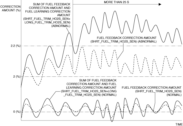
P2096:00
• If a condition in which the feedback correction amount from the HO2S signal is large (fuel injection amount being increased) continues for the specified time ( 25 s), the PCM determines a feedback correction amount malfunction and stores a DTC.
• A condition in which the fuel feedback correction amount (SHRT_FUEL_TRIM_HO2S_SEN) for the HO2S is the specified value ( 2 %) or more and the sum (SHRT_FUEL_TRIM_HO2S_SEN+LONG_FUEL_TRIM_HO2S_SEN) of the fuel feedback correction amount and the fuel learning correction amount is the specified value ( 2.2 %) or more continues for a period of 25 s.
am3zzw00033564
|
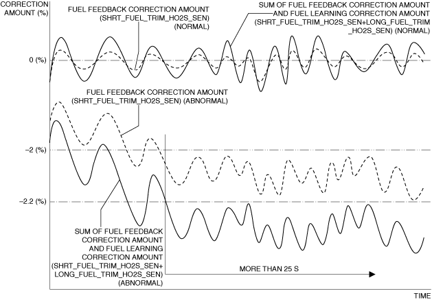
P2097:00
• If a condition in which the feedback correction amount from the HO2S signal is small (fuel injection amount being decreased) continues for the specified time ( 25 s), the PCM determines a feedback correction amount malfunction and stores a DTC.
• A condition in which the fuel feedback correction amount (SHRT_FUEL_TRIM_HO2S_SEN) for the HO2S is the specified value ( −2 %) or less and the sum (SHRT_FUEL_TRIM_HO2S_SEN+LONG_FUEL_TRIM_HO2S_SEN) of the fuel feedback correction amount and the fuel learning correction amount is the specified value ( −2.2 %) or less continues for a period of 25 s.
am3zzw00033565
|
Repeatability Verification Procedure
1. Warm up the engine to allow the engine coolant temperature to reach 80 °C {176 °F} or more.
2. Shift to 3rd gear and drive the vehicle for 20 min at an engine speed of 1,500 rpm or more and a vehicle speed of 50 km/h {31 mph} or more.
-
Note
-
• Match the engine coolant temperature in the recorded freeze frame data/snapshot data, the vehicle speed, and engine speed values to the best extent possible while driving the vehicle.
3. Try to reproduce the malfunction by driving the vehicle for 5 min based on the values in the freeze frame data/snapshot data.
PID Item/Simulation Item Used In Diagnosis
PID/DATA monitor item table
|
PIDs |
Reference |
|---|---|
|
EQUIVALENCE_RATIO_COMD
|
|
|
A/F_SEN_CUR
|
|
|
HO2S_OUT_VOLT
|
Simulation item table
|
Simulation items |
Reference |
|---|---|
|
PRG_DUTY
|
|
|
INJ
|
Function Inspection Using M-MDS
|
Step |
Inspection |
Results |
Action |
|---|---|---|---|
|
1
|
PURPOSE: VERIFY RELATED REPAIR INFORMATION OR SERVICE INFORMATION AVAILABILITY
• Verify related Service Bulletins, on-line repair information, or Service Information availability.
• Is any related Information available?
|
Yes
|
Perform repair or diagnosis according to the available information.
• If the vehicle is not repaired, go to the next step.
|
|
No
|
Go to the next step.
|
||
|
2
|
PURPOSE: IDENTIFY TRIGGER DTC FOR FREEZE FRAME DATA
• Is the DTC P2096:00 or P2097:00 on freeze frame data?
|
Yes
|
Go to the next step.
|
|
No
|
Go to the troubleshooting procedure for DTC on freeze frame data.
|
||
|
3
|
PURPOSE: RECORD VEHICLE STATUS WHEN DTC WAS DETECTED TO UTILIZE WITH REPEATABILITY VERIFICATION
• Record the freeze frame data/snapshot data.
|
—
|
Go to the next step.
|
|
4
|
PURPOSE: VERIFICATION IF MALFUNCTION CAUSED BY LACK OF FUEL
• Verify the snapshot data FLI. (See SNAPSHOT DATA TABLE [PCM (SKYACTIV-G)].)
• Is the snapshot data FLI 5% or less?
|
Yes
|
Refill the fuel.
Go to Troubleshooting Diagnostic Procedure to perform the repair completion verification.
|
|
No
|
Go to the next step.
|
||
|
5
|
PURPOSE: VERIFY DTCs FOR FUEL PRESSURE SENSOR
• Perform the DTC inspection for the PCM. (See DTC INSPECTION.)
• Are any of the following DTCs displayed?
|
Yes
|
Repair the malfunctioning location according to the applicable DTC troubleshooting.
Go to the next step.
|
|
No
|
Go to the next step.
|
||
|
6
|
PURPOSE: VERIFY DTCs FOR ELECTRIC VARIABLE VALVE TIMING CONTROL SYSTEM AND HYDRAULIC VARIABLE VALVE TIMING
• Perform the DTC inspection for the PCM. (See DTC INSPECTION.)
• Are any of the following DTCs displayed?
|
Yes
|
Repair the malfunctioning location according to the applicable DTC troubleshooting.
Go to the next step.
|
|
No
|
Go to the next step.
|
||
|
7
|
PURPOSE: VERIFY DTCs FOR MISFIRE
• Perform the DTC inspection for the PCM. (See DTC INSPECTION.)
• Are any of the following DTCs displayed?
|
Yes
|
Repair the malfunctioning location according to the applicable DTC troubleshooting.
Go to the next step.
|
|
No
|
Go to the next step.
|
||
|
8
|
PURPOSE: VERIFY A/F SENSOR AND HO2S INPUT SIGNAL
• Start the engine and warm it up completely.
• Access the following PIDs using the M-MDS: (See PID/DATA MONITOR INSPECTION.)
• Drive the vehicle under the following conditions.
• Is the displayed PID value as follows?
|
Yes
|
Go to Step 10.
|
|
No
|
Go to the next step.
|
||
|
9
|
PURPOSE: INSPECT RELATED SENSOR WIRING HARNESS AND CONNECTOR
• Access the following PIDs using the M-MDS: (See PID/DATA MONITOR INSPECTION.)
• When the PCM, A/F sensor and HO2S are shaken, does the PID value include a PID item which has changed?
|
Yes
|
Inspect the related wiring harness and connector.
• Repair or replace the malfunctioning location.
Go to Troubleshooting Diagnostic Procedure to perform the repair completion verification.
|
|
No
|
Go to Troubleshooting Diagnostic Procedure to perform the procedure from Step 1.
|
||
|
10
|
PURPOSE: VERIFY IF MALFUNCTION CAUSED BY FUEL INJECTOR IMPROPER OPERATION
• Start the engine and idle it.
• Access the following simulation items using the M-MDS: (See SIMULATION INSPECTION.)
• Using the simulation function, can the change in engine speed be verified when operation of each of the fuel injectors is stopped?
|
Yes
|
Go to the next step.
|
|
No
|
Go to Troubleshooting Diagnostic Procedure to perform the procedure from Step 3.
|
||
|
11
|
PURPOSE: VERIFY IF MALFUNCTION CAUSED BY PURGE SOLENOID VALVE IMPROPER OPERATION
• Start the engine and idle it.
• Access the EQUIVALENCE_RATIO_COMD PID and simulation item PRG_DUTY using the M-MDS. (See PID/DATA MONITOR INSPECTION.) (See SIMULATION INSPECTION.)
• Using the simulation function, does the EQUIVALENCE_RATIO_COMD PID value change when the purge solenoid valve is opened/closed?
|
Yes
|
Go to Troubleshooting Diagnostic Procedure to perform the procedure from Step 5.
|
|
No
|
Go to Troubleshooting Diagnostic Procedure to perform the procedure from Step 4.
|
Troubleshooting Diagnostic Procedure
Intention of troubleshooting procedure
• Step 1—2
-
― Perform inspection of HO2S and A/F sensor signal related parts.
• Step 3
-
― Perform a fuel injector control system inspection.
• Step 4
-
― Perform a purge control system inspection.
• Step 5—6
-
― Perform inspection of fuel line.
• Step 7—12
-
― Perform inspection of each separate part.
• Repair completion verification
-
― Verify that the primary malfunction is resolved and there are no other malfunctions.
|
Step |
Inspection |
Results |
Action |
|---|---|---|---|
|
1
|
PURPOSE: VERIFY IF HO2S IS INSTALLED CORRECTLY
• Verify the HO2S installation condition. (See HEATED OXYGEN SENSOR (HO2S) REMOVAL/INSTALLATION [SKYACTIV-G (WITH CYLINDER DEACTIVATION (US))].) (See HEATED OXYGEN SENSOR (HO2S) REMOVAL/INSTALLATION [SKYACTIV-G (WITHOUT CYLINDER DEACTIVATION (US))].)
• Is the installation condition normal?
|
Yes
|
Go to the next step.
|
|
No
|
Correctly install the HO2S and perform the repair completion verification.
|
||
|
2
|
PURPOSE: VERIFY IF A/F SENSOR IS INSTALLED CORRECTLY
• Verify the A/F sensor installation condition. (See AIR FUEL RATIO (A/F) SENSOR REMOVAL/INSTALLATION [SKYACTIV-G (WITH CYLINDER DEACTIVATION (US))].) (See AIR FUEL RATIO (A/F) SENSOR REMOVAL/INSTALLATION [SKYACTIV-G (WITHOUT CYLINDER DEACTIVATION (US))].)
• Is the installation condition normal?
|
Yes
|
Replace the A/F sensor and/or HO2S and perform the repair completion verification.
(See AIR FUEL RATIO (A/F) SENSOR REMOVAL/INSTALLATION [SKYACTIV-G (WITH CYLINDER DEACTIVATION (US))].)
(See AIR FUEL RATIO (A/F) SENSOR REMOVAL/INSTALLATION [SKYACTIV-G (WITHOUT CYLINDER DEACTIVATION (US))].)
|
|
No
|
Correctly install the A/F sensor and perform the repair completion verification.
|
||
|
3
|
PURPOSE: INSPECT FUEL INJECTOR OPERATION
• In Step 10 of the function inspection using the M-MDS, perform a fail-safe injector operation inspection on the cylinders in which engine speed fluctuation could not be verified. (See FUEL INJECTOR INSPECTION [SKYACTIV-G (WITH CYLINDER DEACTIVATION (US))].) (See FUEL INJECTOR INSPECTION [SKYACTIV-G (WITHOUT CYLINDER DEACTIVATION (US))].)
• Is there any malfunction?
|
Yes
|
Repair or replace the malfunctioning location and perform the repair completion verification.
|
|
No
|
Go to the next step.
|
||
|
4
|
PURPOSE: INSPECT PURGE SOLENOID VALVE FOR MALFUNCTION
• Inspect the applicable part. (See PURGE SOLENOID VALVE INSPECTION [SKYACTIV-G (WITH CYLINDER DEACTIVATION (US))].) (See PURGE SOLENOID VALVE INSPECTION [SKYACTIV-G (WITHOUT CYLINDER DEACTIVATION (US))].)
• Is the part normal?
|
Yes
|
Go to the next step.
|
|
No
|
Repair or replace the malfunctioning location and perform the repair completion verification.
|
||
|
5
|
PURPOSE: VERIFY IF MALFUNCTION RELATED TO FUEL LEAK FROM FUEL SYSTEM AFFECTS DIAGNOSTIC RESULTS
• Visually inspect for leakage from fuel line between fuel distributor and fuel pump.
• Is there any leakage?
|
Yes
|
Repair or replace the malfunctioning location and perform the repair completion verification.
|
|
No
|
Go to the next step.
|
||
|
6
|
PURPOSE: INSPECT FUEL LINE (LOW-SIDE)
• Inspect for leakage or restriction in the fuel line (low-side).
• Is there any malfunction?
|
Yes
|
Repair or replace the malfunctioning location and perform the repair completion verification.
|
|
No
|
Go to the next step.
|
||
|
7
|
PURPOSE: VERIFY IF HO2S IS INSTALLED CORRECTLY
• Verify the HO2S installation condition. (See HEATED OXYGEN SENSOR (HO2S) REMOVAL/INSTALLATION [SKYACTIV-G (WITH CYLINDER DEACTIVATION (US))].) (See HEATED OXYGEN SENSOR (HO2S) REMOVAL/INSTALLATION [SKYACTIV-G (WITHOUT CYLINDER DEACTIVATION (US))].)
• Is the installation condition normal?
|
Yes
|
Go to the next step.
|
|
No
|
Correctly install the HO2S and perform the repair completion verification.
|
||
|
8
|
PURPOSE: VERIFY IF A/F SENSOR IS INSTALLED CORRECTLY
• Verify the A/F sensor installation condition. (See AIR FUEL RATIO (A/F) SENSOR REMOVAL/INSTALLATION [SKYACTIV-G (WITH CYLINDER DEACTIVATION (US))].) (See AIR FUEL RATIO (A/F) SENSOR REMOVAL/INSTALLATION [SKYACTIV-G (WITHOUT CYLINDER DEACTIVATION (US))].)
• Is the installation condition normal?
|
Yes
|
Go to the next step.
|
|
No
|
Correctly install the A/F sensor and perform the repair completion verification.
|
||
|
9
|
PURPOSE: INSPECT EXHAUST SYSTEM FOR LEAKAGE
• Verify the exhaust gas leakage from the exhaust system. (between A/F sensor and HO2S)
• Is there any malfunction?
|
Yes
|
Repair or replace the malfunctioning location and perform the repair completion verification.
|
|
No
|
Go to the next step.
|
||
|
10
|
PURPOSE: INSPECT MAP SENSOR FOR MALFUNCTION
• Inspect the applicable part. (See MANIFOLD ABSOLUTE PRESSURE (MAP) SENSOR INSPECTION [SKYACTIV-G (WITH CYLINDER DEACTIVATION (US))].) (See MANIFOLD ABSOLUTE PRESSURE (MAP) SENSOR INSPECTION [SKYACTIV-G (WITHOUT CYLINDER DEACTIVATION (US))].)
• Is the part normal?
|
Yes
|
Go to the next step.
|
|
No
|
Repair or replace the malfunctioning location and perform the repair completion verification.
|
||
|
11
|
PURPOSE: INSPECT MAF SENSOR FOR MALFUNCTION
• Inspect the applicable part. (See MASS AIR FLOW (MAF) SENSOR INSPECTION [SKYACTIV-G (WITH CYLINDER DEACTIVATION (US))].) (See MASS AIR FLOW (MAF) SENSOR INSPECTION [SKYACTIV-G (WITHOUT CYLINDER DEACTIVATION (US))].)
• Is the part normal?
|
Yes
|
Go to the next step.
|
|
No
|
Repair or replace the malfunctioning location and perform the repair completion verification.
|
||
|
12
|
PURPOSE: INSPECT AIR CLEANER ELEMENT FOR MALFUNCTION
• Remove the air cleaner element with the engine is running. (See AIR CLEANER ELEMENT REMOVAL/INSTALLATION [SKYACTIV-G (WITH CYLINDER DEACTIVATION (US))].) (See AIR CLEANER ELEMENT REMOVAL/INSTALLATION [SKYACTIV-G (WITHOUT CYLINDER DEACTIVATION (US))].)
• Does the engine speed increase?
|
Yes
|
Inspect the air cleaner element.
• If there is any malfunction:
• If there is no malfunction:
|
|
No
|
Go to the next step.
|
||
|
Repair completion verification 1
|
PURPOSE: VERIFY THAT VEHICLE IS REPAIRED
• Install/connect the part removed/disconnected during the troubleshooting procedure.
• Clear the DTC recorded in the memory. (See CLEARING DTC.)
• Replicate the vehicle conditions at the time the DTC was detected using the following procedure.
• Perform the DTC inspection for the PCM. (See DTC INSPECTION.)
• Is the same Pending DTC present?
|
Yes
|
Refer to the controller area network (CAN) malfunction diagnosis flow to inspect for a CAN communication error.
If the CAN communication is normal, perform the diagnosis from Step 1.
• If the malfunction recurs, replace the PCM, then go to the next step. (See PCM REMOVAL/INSTALLATION [SKYACTIV-G (WITH CYLINDER DEACTIVATION (US))].) (See PCM REMOVAL/INSTALLATION [SKYACTIV-G (WITHOUT CYLINDER DEACTIVATION (US))].)
|
|
No
|
Go to the next step.
|
||
|
Repair completion verification 2
|
PURPOSE: VERIFY IF OTHER DTCs DISPLAYED
• Perform the DTC inspection. (See DTC INSPECTION.)
• Are any other DTCs displayed?
|
Yes
|
Repair the malfunctioning location according to the applicable DTC troubleshooting.
|
|
No
|
DTC troubleshooting completed.
|