DTC P0300:00 [PCM (SKYACTIV-G (US))]
DTC P0300:00 [PCM (SKYACTIV-G (US))]
SM2565564
id0102t47032u0
-
Note
-
• To determine the malfunctioning part, proceed with the diagnostics from “Function Inspection Using M-MDS”.
Details On DTCs
|
Description |
Random misfire detected |
|
|---|---|---|
|
Detection condition
|
Determination conditions
|
• Any one of the following conditions is met:
|
|
Preconditions
|
• Battery voltage: 9—18 V *1
• Engine speed: 500—6,700 rpm *1
• Engine coolant temperature: −10 °C {14 °F} or more or 21 °C {70 °F} or more *1 (standard differs depending on engine coolant temperature at engine start)
• Not cranking
• Not stalling
• Fuel-cut control not implemented
• Crankshaft installation tolerance learning completed
• Engine condition is stabilized (not directly after gear change)
*1: Standard can be verified by displaying PIDs using M-MDS
|
|
|
Malfunction determination period
|
• 200 rotations of crankshaft (misfire which may damage catalytic converter)
• 1,000 rotations of crankshaft (misfire going against emission regulations)
|
|
|
Drive cycle
|
• 2
|
|
|
Self test type
|
• CMDTC self test
|
|
|
Sensor used
|
• CKP sensor
• MAF sensor
• MAP sensor
|
|
|
Fail-safe function
|
• Limits intake air amount
• Implement fuel-cut control (if the catalytic converter may be damaged, perform fuel-cut on cylinder misfiring the most).
|
|
|
Vehicle status when DTCs are output
|
• Misfiring which may damage catalytic converter (number of drive cycles: 1):
• Drive cycle directly after above drive cycle (number of drive cycles: 2):
• Rough idling, poor acceleration, stalling
|
|
|
Possible cause
|
• Improper operation of ignition system
• Fuel injector malfunction
• Erratic signal to PCM
• Poor drive belt assembly or adhesion of oil
• Drive belt auto tensioner malfunction
• Air leakage from intake air system (between intake manifold and cylinder head)
• Engine malfunction
• PCM malfunction
|
|
System Wiring Diagram
• Not applicable.
Function Explanation (DTC Detection Outline)
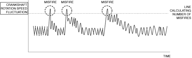
• The PCM detects the crankshaft rotation speed based on the crankshaft position sensor signal. If there is a small amount of fluctuation in crankshaft rotation speed due to the effect of combustion of each cylinder while the engine is rotating and a misfire occurs in any of the pistons, the crankshaft rotation speed will change suddenly. The PCM adds the number of changes in sudden rotation speed (misfire rate) to each specified crankshaft rotation speed, and if the misfire rate exceeds a certain value, a DTC is recorded.
am3zzw00033725
|
Repeatability Verification Procedure
1. Drive the vehicle at a speed of 40 km/h {25 mph} or more.
2. Shift to 3rd gear and rapidly accelerate the vehicle to 60 km/h {37 mph} (to execute misfire monitor).
3. Release the accelerator pedal and decelerate the vehicle to 40 km/h {25 mph}.
4. Repeat Step 1 to 3 operations above 5 times.
-
Note
-
• Match the engine coolant temperature in the recorded freeze frame data/snapshot data, the vehicle speed, and engine speed values to the best extent possible while driving the vehicle.
5. Try to reproduce the malfunction by driving the vehicle for 5 min based on the values in the freeze frame data/snapshot data.
PID Item/Simulation Item Used In Diagnosis
PID/DATA monitor item table
|
PIDs |
Reference |
|---|---|
|
APP1
|
|
|
APP2
|
|
|
ECT
|
|
|
ECT_VOLT
|
|
|
IAT
|
|
|
MAF
|
|
|
MAP
|
|
|
MAP_VOLT
|
|
|
MISFIRE_CYL1_CAT
|
|
|
MISFIRE_CYL2_CAT
|
|
|
MISFIRE_CYL3_CAT
|
|
|
MISFIRE_CYL4_CAT
|
|
|
MISFIRE_CYL1_EMI
|
|
|
MISFIRE_CYL2_EMI
|
|
|
MISFIRE_CYL3_EMI
|
|
|
MISFIRE_CYL4_EMI
|
|
|
ENG_RPM
|
|
|
TP_RELAT
|
|
|
VSS
|
Function Inspection Using M-MDS
|
Step |
Inspection |
Results |
Action |
|---|---|---|---|
|
1
|
PURPOSE: VERIFY RELATED REPAIR INFORMATION OR SERVICE INFORMATION AVAILABILITY
• Verify related Service Bulletins, on-line repair information, or Service Information availability.
• Is any related Information available?
|
Yes
|
Perform repair or diagnosis according to the available information.
• If the vehicle is not repaired, go to the next step.
|
|
No
|
Go to the next step.
|
||
|
2
|
PURPOSE: IDENTIFY TRIGGER DTC FOR FREEZE FRAME DATA
• Is the DTC P0300:00 on freeze frame data?
|
Yes
|
Go to the next step.
|
|
No
|
Go to the troubleshooting procedure for DTC on freeze frame data.
|
||
|
3
|
PURPOSE: RECORD VEHICLE STATUS WHEN DTC WAS DETECTED TO UTILIZE WITH REPEATABILITY VERIFICATION
• Record the freeze frame data/snapshot data and diagnostic monitoring test results (misfire related).
|
—
|
Go to the next step.
|
|
4
|
PURPOSE: INSPECT FOR OTHER RELATED DTCs
• Perform the DTC inspection for the PCM. (See DTC INSPECTION.)
• Are any other DTCs displayed?
|
Yes
|
Repair the malfunctioning location according to the applicable DTC troubleshooting.
|
|
No
|
Go to the next step.
|
||
|
5
|
PURPOSE: VERIFY IF THERE IS PID ITEM CAUSING DRASTIC CHANGES OF ACCELERATION FLUCTUATION BY INPUT SIGNAL TO PCM
• Start the engine.
• Access the following PIDs using the M-MDS: (See PID/DATA MONITOR INSPECTION.)
• Is there a PID item affected by acceleration fluctuation?
|
Yes
|
Inspect the suspected sensor and related wiring harness.
• If there is any malfunction:
• If there is no malfunction:
|
|
No
|
Go to the next step.
|
||
|
6
|
PURPOSE: RECORD NUMBER OF CURRENT MISFIRES DURING NO LOAD TO SPECIFY MISFIRING CYLINDER
• Start the engine.
• Verify all accessory loads (A/C, headlights, blower fan, rear window defogger) are off.
• Under no-load conditions (P or N position (ATX)/neutral (MTX)), increase the engine speed to 3,000 rpm and hold for 30 s.
• Verify the number of misfires.
• Can a misfire be verified?
|
Yes
|
Record each of the verified values, then go to the next step.
|
|
No
|
Go to Step 9.
|
||
|
7
|
PURPOSE: VERIFY IF MISFIRE CAUSE IS BAD SPARK PLUGS
• Switch the spark plugs on a cylinder that is misfiring and a cylinder that is not misfiring. (See SPARK PLUG REMOVAL/INSTALLATION [SKYACTIV-G (WITH CYLINDER DEACTIVATION (US))].) (See SPARK PLUG REMOVAL/INSTALLATION [SKYACTIV-G (WITHOUT CYLINDER DEACTIVATION (US))].)
• Start the engine.
• Verify all accessory loads (A/C, headlights, blower fan, rear window defogger) are off.
• Under no-load conditions (P or N position (ATX)/neutral (MTX)), increase the engine speed to 3,000 rpm and hold for 30 s.
• Verify the number of misfires.
• Is there a change from the recorded number of misfires in Step 6?
|
Yes
|
Go to Troubleshooting Diagnostic Procedure to perform the procedure from Step 1.
|
|
No
|
Go to the next step.
|
||
|
8
|
PURPOSE: VERIFY IF MISFIRE CAUSE IS BAD IGNITION COIL
• Switch the ignition coils on a cylinder that is misfiring and a cylinder that is not misfiring. (See IGNITION COIL/ION SENSOR REMOVAL/INSTALLATION [SKYACTIV-G (WITH CYLINDER DEACTIVATION (US))].) (See IGNITION COIL/ION SENSOR REMOVAL/INSTALLATION [SKYACTIV-G (WITHOUT CYLINDER DEACTIVATION (US))].)
• Start the engine.
• Verify all accessory loads (A/C, headlights, blower fan, rear window defogger) are off.
• Under no-load conditions (P or N position (ATX)/neutral (MTX)), increase the engine speed to 3,000 rpm and hold for 30 s.
• Verify the number of misfires.
• Is there a change from the recorded number of misfires in Step 6?
|
Yes
|
Go to Troubleshooting Diagnostic Procedure to perform the procedure from Step 2.
|
|
No
|
Go to Troubleshooting Diagnostic Procedure to perform the procedure from Step 3.
|
||
|
9
|
PURPOSE: RECORD NUMBER OF CURRENT MISFIRES WHILE DRIVING UNDER LOAD TO SPECIFY MISFIRING CYLINDER
• Start the engine.
• Verify the number of misfires while the vehicle is being driven for 1 min under the condition of the freeze frame data recorded in Step 3.
• Can a misfire be verified?
|
Yes
|
Record each of the verified values, then go to the next step.
|
|
No
|
Referring to the service questioning results, verify the misfire rate again with the driving mode data added before recording the freeze frame data/snapshot data.
|
||
|
10
|
PURPOSE: VERIFY IF MISFIRE CAUSE IS BAD SPARK PLUGS
• Switch the spark plugs on a cylinder that is misfiring and a cylinder that is not misfiring. (See SPARK PLUG REMOVAL/INSTALLATION [SKYACTIV-G (WITH CYLINDER DEACTIVATION (US))].) (See SPARK PLUG REMOVAL/INSTALLATION [SKYACTIV-G (WITHOUT CYLINDER DEACTIVATION (US))].)
• Start the engine.
• Verify the number of misfires while the vehicle is being driven for 1 min under the driving conditions in which misfires were verified in Step 9.
• Is there a change from the recorded number of misfires in Step 9?
|
Yes
|
Go to Troubleshooting Diagnostic Procedure to perform the procedure from Step 1.
|
|
No
|
Go to the next step.
|
||
|
11
|
PURPOSE: VERIFY IF MISFIRE CAUSE IS BAD IGNITION COIL
• Switch the ignition coils on a cylinder that is misfiring and a cylinder that is not misfiring. (See IGNITION COIL/ION SENSOR REMOVAL/INSTALLATION [SKYACTIV-G (WITH CYLINDER DEACTIVATION (US))].) (See IGNITION COIL/ION SENSOR REMOVAL/INSTALLATION [SKYACTIV-G (WITHOUT CYLINDER DEACTIVATION (US))].)
• Start the engine.
• Verify the number of misfires while the vehicle is being driven for 1 min under the driving conditions in which misfires were verified in Step 9.
• Is there a change from the recorded number of misfires in Step 9?
|
Yes
|
Go to Troubleshooting Diagnostic Procedure to perform the procedure from Step 2.
|
|
No
|
Go to Troubleshooting Diagnostic Procedure to perform the procedure from Step 3.
|
Troubleshooting Diagnostic Procedure
Intention of troubleshooting procedure
• Step 1—2
-
― Perform an ignition system parts inspection.
• Step 3
-
― Perform a fuel injector control system inspection.
• Step 4—9
-
― Perform an inspection of parts which may be affected by misfire except for ignition-related parts and fuel injection control-related parts.
• Repair completion verification
-
― Verify that primary malfunction is resolved and there are no other malfunctions.
|
Step |
Inspection |
Results |
Action |
|---|---|---|---|
|
1
|
PURPOSE: INSPECT SPARK PLUG FOR MALFUNCTION
• Inspect the applicable part. (See SPARK PLUG INSPECTION [SKYACTIV-G (WITH CYLINDER DEACTIVATION (US))].) (See SPARK PLUG INSPECTION [SKYACTIV-G (WITHOUT CYLINDER DEACTIVATION (US))].)
• Is the part normal?
|
Yes
|
Go to the next step.
|
|
No
|
Repair or replace the malfunctioning location and perform the repair completion verification.
|
||
|
2
|
PURPOSE: INSPECT IGNITION COIL FOR MALFUNCTION
• Inspect the applicable part. (See IGNITION COIL INSPECTION [SKYACTIV-G (WITH CYLINDER DEACTIVATION (US))].) (See IGNITION COIL INSPECTION [SKYACTIV-G (WITHOUT CYLINDER DEACTIVATION (US))].)
• Is the part normal?
|
Yes
|
Go to the next step.
|
|
No
|
Repair or replace the malfunctioning location and perform the repair completion verification.
|
||
|
3
|
PURPOSE: INSPECT FUEL INJECTOR FOR MALFUNCTION
• Inspect the applicable part. (See FUEL INJECTOR INSPECTION [SKYACTIV-G (WITH CYLINDER DEACTIVATION (US))].) (See FUEL INJECTOR INSPECTION [SKYACTIV-G (WITHOUT CYLINDER DEACTIVATION (US))].)
• Is the part normal?
|
Yes
|
Go to the next step.
|
|
No
|
Repair or replace the malfunctioning location and perform the repair completion verification.
|
||
|
4
|
PURPOSE: VERIFY IF MALFUNCTION RELATED TO INTAKE-AIR SYSTEM IS CAUSE OF MISFIRE
• Visually inspect for loose, cracked or damaged hoses on intake air system.
• Is there any malfunction?
|
Yes
|
Repair or replace the malfunctioning location and perform the repair completion verification.
|
|
No
|
Go to the next step.
|
||
|
5
|
PURPOSE: VERIFY IF POOR DRIVE BELT ASSEMBLY IS CAUSE OF MISFIRE
• Verify the condition of the drive belt assembly. (See DRIVE BELT INSPECTION [SKYACTIV-G (WITH CYLINDER DEACTIVATION (US))].) (See DRIVE BELT INSPECTION [SKYACTIV-G (WITHOUT CYLINDER DEACTIVATION (US))].)
• Is there any malfunction?
|
Yes
|
Assemble drive belt correctly and perform the repair completion verification.
|
|
No
|
Go to the next step.
|
||
|
6
|
PURPOSE: VERIFY IF FOREIGN MATTER ON DRIVE BELT IS CAUSE OF MISFIRE
• Verify if oil is on the drive belt.
• Is there foreign matter on the drive belt?
|
Yes
|
Remove the foreign matter on the drive belt and perform the repair completion verification.
|
|
No
|
Go to the next step.
|
||
|
7
|
PURPOSE: INSPECT DRIVE BELT AUTO TENSIONER FOR MALFUNCTION
• Inspect the applicable part. (See DRIVE BELT AUTO TENSIONER INSPECTION [SKYACTIV-G (WITH CYLINDER DEACTIVATION (US))].) (See DRIVE BELT AUTO TENSIONER INSPECTION [SKYACTIV-G (WITHOUT CYLINDER DEACTIVATION (US))].)
• Is the part normal?
|
Yes
|
Go to the next step.
|
|
No
|
Repair or replace the malfunctioning location and perform the repair completion verification.
|
||
|
8
|
PURPOSE: VERIFY IF MALFUNCTION RELATED TO ENGINE COMPRESSION IS CAUSE OF MISFIRE
• Inspect the engine compression. (See COMPRESSION INSPECTION [SKYACTIV-G (WITH CYLINDER DEACTIVATION (US))].) (See COMPRESSION INSPECTION [SKYACTIV-G (WITHOUT CYLINDER DEACTIVATION (US))].)
• Are compression pressures within specification?
|
Yes
|
Go to the next step.
|
|
No
|
Replace or overhaul the engine and perform the repair completion verification.
|
||
|
9
|
PURPOSE: VERIFY IF MALFUNCTION RELATED TO SEALING OF ENGINE UNIT (COMBUSTION CHAMBER AND ENGINE COOLANT PASSAGE) IS CAUSE OF MISFIRE
• Perform the “ENGINE COOLANT LEAKAGE INSPECTION”. (See ENGINE COOLANT LEAKAGE INSPECTION [SKYACTIV-G (WITH CYLINDER DEACTIVATION (US))].) (See ENGINE COOLANT LEAKAGE INSPECTION [SKYACTIV-G (WITHOUT CYLINDER DEACTIVATION (US))].)
• Does the radiator cap tester needle drop even though there is no engine coolant leakage from the radiator or the hoses?
|
Yes
|
Engine coolant leakage from the engine (between the combustion chamber and the engine coolant passage) may have occurred.
• Verify the conditions of the gasket and the cylinder head.
|
|
No
|
Go to the next step.
|
||
|
Repair completion verification 1
|
PURPOSE: VERIFY THAT VEHICLE IS REPAIRED
• Install/connect the part removed/disconnected during the troubleshooting procedure.
• Clear the DTC recorded in the memory. (See CLEARING DTC.)
• Replicate the vehicle conditions at the time the DTC was detected using the following procedure.
• Perform the DTC inspection for the PCM. (See DTC INSPECTION.)
• Is the same Pending DTC present?
|
Yes
|
Refer to the controller area network (CAN) malfunction diagnosis flow to inspect for a CAN communication error.
If the CAN communication is normal, perform the diagnosis from Step 1.
• If the malfunction recurs, replace the PCM, then go to the next step. (See PCM REMOVAL/INSTALLATION [SKYACTIV-G (WITH CYLINDER DEACTIVATION (US))].) (See PCM REMOVAL/INSTALLATION [SKYACTIV-G (WITHOUT CYLINDER DEACTIVATION (US))].)
|
|
No
|
Go to the next step.
|
||
|
Repair completion verification 2
|
PURPOSE: VERIFY IF OTHER DTCs DISPLAYED
• Perform the DTC inspection. (See DTC INSPECTION.)
• Are any other DTCs displayed?
|
Yes
|
Repair the malfunctioning location according to the applicable DTC troubleshooting.
|
|
No
|
DTC troubleshooting completed.
|