STEERING GEAR AND LINKAGE INSPECTION [(US)]
STEERING GEAR AND LINKAGE INSPECTION [(US)]
SM2335539
id0613008020x1
-
Caution
-
• Performing the following procedures could cause an open circuit in the front ABS wheel-speed sensor wiring harness if it is pulled by mistake. Before servicing, disconnect the front ABS wheel-speed sensor and set it aside so that the wiring harness will not be pulled by mistake.• If the steering wheel rotates after the steering shaft and the steering gear and linkage are disconnected, the internal parts of the clock spring could be damaged. Disconnect the steering shaft and then secure the steering wheel with tape or cable so that it does not rotate.• Do not allow the dust boot of the front stabilizer control link to touch the body, the front shock absorber and coil spring, and the hand tool. Otherwise, the dust boot of the front stabilizer control link could be damaged.
1.Remove the wheel and tire. (See WHEEL AND TIRE REMOVAL/INSTALLATION.)
2.Disconnect the rubber from the bracket.
am3zzw00023150
|
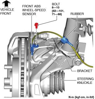
3.Disconnect the front ABS wheel-speed sensor wiring harness on the steering knuckle and set it aside so that it does not interfere with the servicing.
4.Remove the tunnel cover. (See EXHAUST SYSTEM REMOVAL/INSTALLATION [SKYACTIV-G (WITHOUT CYLINDER DEACTIVATION (US))].) (See EXHAUST SYSTEM REMOVAL/INSTALLATION [SKYACTIV-G (WITH CYLINDER DEACTIVATION (US))].)
5.Remove the following parts.
- (1)Front under cover No.1 (See FRONT UNDER COVER No.1 REMOVAL/INSTALLATION.)
- (2)Front under cover No.2 (See FRONT UNDER COVER No.2 REMOVAL/INSTALLATION.)
6. Disconnect the tie-rod end from the steering knuckle. (See TIE-ROD END REPLACEMENT.)
7.Disconnect the front lower arm ball joint from the steering knuckle. (See FRONT LOWER ARM REMOVAL/INSTALLATION [(US)].)
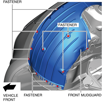
8.Remove the fastener shown in the figure and slightly bend back the front mudguard.
am3zzw00023151
|
9.Remove the front deflector. (See DEFLECTOR REMOVAL/INSTALLATION.)
10.Remove the front splash shield. (See SPLASH SHIELD REMOVAL/INSTALLATION.)
11.Remove the joint cover. (See INTERMEDIATE SHAFT REMOVAL/INSTALLATION [(US)].)
12.Disconnect the intermediate shaft from the steering gear and linkage. (See INTERMEDIATE SHAFT REMOVAL/INSTALLATION [(US)].)
13.Remove the front crossmember component. (See FRONT CROSSMEMBER REMOVAL/INSTALLATION [(US)].)
14.Remove the hole cover No.1 and hole cover No.2. (See FRONT CROSSMEMBER REMOVAL/INSTALLATION [(US)].)
15.Remove the steering gear and linkage from the front crossmember component. (See STEERING GEAR AND LINKAGE REMOVAL/INSTALLATION [(US)].)
16.Remove the locknuts, tie-rod ends, boot clamps, boot bands, and boots from the steering gear and linkage. (See STEERING GEAR AND LINKAGE DISASSEMBLY [(US)].)
17.Measure the pinion shaft rotation torque using a crescent wrench and pull scale. (Measurement speed reference: 5 rpm)
ac8wzw00001514
|
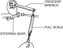
- (1)Install the crescent wrench to the steering gear.
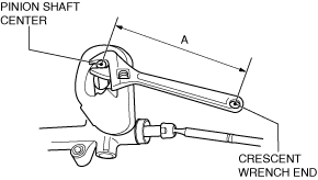
- (2)Measure the distance between the pinion shaft center and the crescent wrench end (point of action of pull scale) shown in the figure and designate this value as A.
-
 ac8wzw00001515
- (3)For the measurement using a crescent wrench, calculate the pinion shaft rotation torque by the following formula.
- Pinion shaft rotation torque (N·m {kgf·cm, in·lbf}) = Pull scale reading (N {kgf, lbf}) x A (m {cm, in})
-
Pinion shaft rotation torque (pinion rotation angle of ±180° from rack center position)
-
0.9—1.5 N·m {9.2—15 kgf·cm, 8.0—13 in·lbf}
-
• If not within the standard, replace the steering gear. (See STEERING GEAR AND LINKAGE ASSEMBLY [(US)].) (See STEERING GEAR AND LINKAGE REMOVAL/INSTALLATION [(US)].)
-