TIE-ROD END REPLACEMENT
TIE-ROD END REPLACEMENT
SM2335532
id061300801200
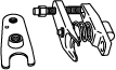
Special service tool (SST)
|
49 T028 3A0
Ball joint puller set
|
 |
Replacement part
|
Snap pin
Quantity: 1
Location of use: Tie-rod end
|
Removal
1.Remove the wheel and tire. (See WHEEL AND TIRE REMOVAL/INSTALLATION.)
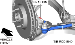
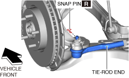
2.Remove the snap pin from the tie-rod end.
am3zzw00023114
|
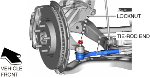
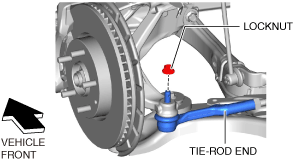
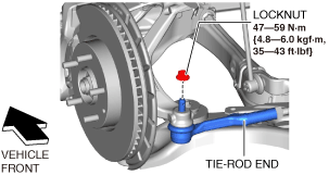
3.Loosen the locknut of the tie-rod end.
am3zzw00023115
|
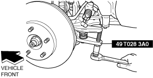
4.Detach the tie-rod end from the steering knuckle using the SST.
ac8wzw00001479
|
5.Remove the locknut of the tie-rod end.
am3zzw00023116
|
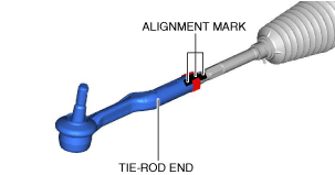
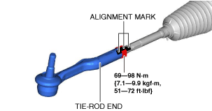
6.Place alignment marks as shown in the figure for reference in tie-rod end assembly.
am3zzw00023117
|
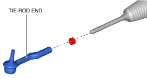
7.Remove the tie-rod end.
am3zzw00023118
|
Installation
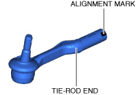
1.Place alignment marks on the new tie-rod end in the same positions as the removed tie-rod end.
am3zzw00023119
|
2.Align the marks that were made before removing the tie-rod end, and assemble the tie-rod end to the tie rod.
am3zzw00023120
|
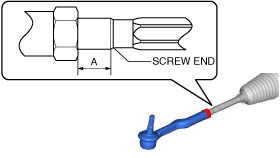
3.Verify that dimension A shown in the figure is within the standard.
am3zzw00027965
|
-
Standard
-
5.8—18.8 mm {0.23—0.74 in}
-
• If not within the standard, make adjustments so that dimension A is within the standard.
4.Install the tie-rod end to the steering knuckle.
am3zzw00023122
|
5.Install a new snap pin.
am3zzw00023123
|
6.Install the wheel and tire. (See WHEEL AND TIRE REMOVAL/INSTALLATION.)
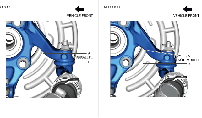
7.Verify that A and B shown in the figure are parallel while the vehicle is on the ground.
am3zzw00033056
|
-
Caution
-
• Install the tie-rod end to the correct position. Otherwise, it could cause cracks on the tie-rod end boot.
-
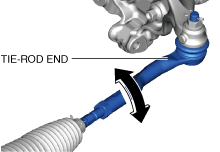
• If the installation position is not correct, perform the adjustment using the following procedure.
-
1. Adjust the tie-rod end by rotating it so that it is at the correct position.
 ac8wzw00003230
-
8.After installation, inspect the front wheel alignment. (See FRONT WHEEL ALIGNMENT [(US)].)