STEERING GEAR AND LINKAGE ASSEMBLY [(US)]
STEERING GEAR AND LINKAGE ASSEMBLY [(US)]
SM2335540
id0613008021x1
Special service tool (SST)
|
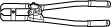
49 JP02 001
Adjustable wrench
|
 |
49 T025 001
Boot clamp crimpers
|
 |
Replacement part
|
Boot band
Quantity: 2
Location of use: Boot
|
Oil and chemical type
|
Grease (Tie rod)
Type: Molywhite
|
Grease (Dust cover)
Type: Maintenance parts
|
-
Caution
-
• If using a vise, secure the steering gear to the vise using a copper plate or cloth to prevent steering gear damage.
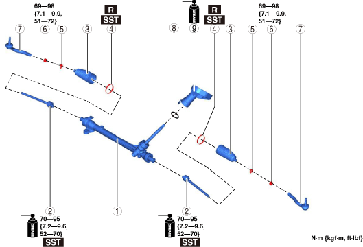
1.Assemble in the order shown in the figure.
2.Install the steering gear and linkage to the front crossmember component. (See STEERING GEAR AND LINKAGE REMOVAL/INSTALLATION [(US)].)
am3zzw00027649
|
|
1
|
Steering gear
|
|
2
|
Tie rod
(See Tie Rod Assembly Note.)
|
|
3
|
Boot
|
|
4
|
Boot band
(See Boot Band Assembly Note.)
|
|
5
|
Boot clamp
|
|
6
|
Locknut
|
|
7
|
Tie-rod end
(See Tie-rod End Assembly Note.)
|
|
8
|
O-ring
|
|
9
|
Dust cover
(See Dust Cover Assembly Note.)
|
Tie Rod Assembly Note
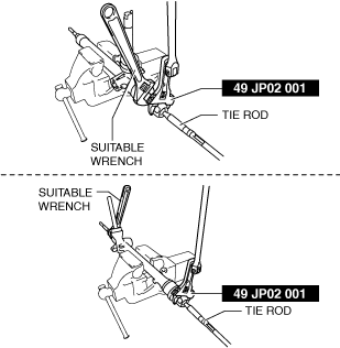
1.Install the SST to the torque wrench as shown in the figure, set it on the tie rod, and then measure dimensions A and L shown in the figure.
adejjw00015170
|
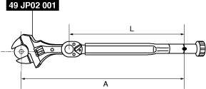
2.Tighten the tie rod using the SST after calculating the tightening torque using the following formula.
am3zzw00033062
|
-
Formula
-
T×(L/A)T: Tightening torqueL: Torque wrench effective lengthA: Dimension A measured in Step 1
Boot Band Assembly Note
1.Assemble the boot band to the boot.
2.Crimp the boot band using the SST.
ac5jjw00002709
|
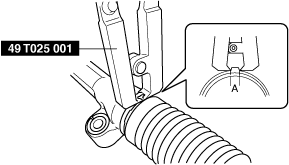
3.Verify that crimp A of the boot band is within the standard.
-
Standard
-
1.5—2.0 mm {0.06—0.08 in}
-
• If crimp A exceeds the standard, decrease the opening width of the SST and crimp the boot band again.• If width A of the crimp is less than the standard, increase the opening width of the SST and crimp a new boot band.
4.Rotate the boot by hand and verify that the boot is securely installed by the boot band.
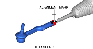
Tie-rod End Assembly Note
1.Align the marks that were made before removing the tie-rod end, and assemble the tie-rod end to the tie rod.
am3zzw00023153
|
-
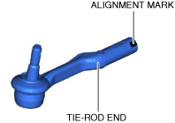
Note
-
• When newly replacing a tie-rod end, place alignment marks on the new part in the same position as the removed tie-rod end.
 am3zzw00023154
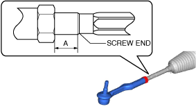
2.Verify that dimension A shown in the figure is within the standard.
am3zzw00027966
|
-
Standard
-
5.8—18.8 mm {0.23—0.74 in}
-
• If not within the standard, make adjustments so that dimension A is within the standard.
Dust Cover Assembly Note
1.Apply grease to the inside of the dust cover.
am3zzw00027650
|
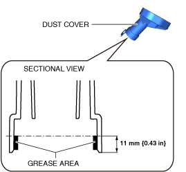
2.Assemble the dust cover to the steering gear.
3.Verify that the dust cover does not rotate.