FRONT CROSSMEMBER REMOVAL/INSTALLATION [(US)]
FRONT CROSSMEMBER REMOVAL/INSTALLATION [(US)]
SM2334998
id0213008010x1
-
Caution
-
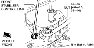
• If the front ABS wheel-speed sensor wiring harness is pulled by mistake when performing this procedure, it could cause open circuit. Before servicing, disconnect the front ABS wheel-speed sensor and set it aside so that the wiring harness will not be pulled by mistake.• If the steering wheel rotates after the steering shaft and the steering gear and linkage are disconnected, the internal parts of the clock spring could be damaged. After disconnecting the steering shaft, secure the steering wheel using tape or cable to prevent it from rotating.• Do not allow the dust boot of the front stabilizer control link to touch the body, the front shock absorber and coil spring, and the hand tool. Otherwise, the dust boot of the front stabilizer control link could be damaged.
1.Remove the wheel and tire. (See WHEEL AND TIRE REMOVAL/INSTALLATION.)
2.Disconnect the rubber from the bracket.
am3zzw00023026
|
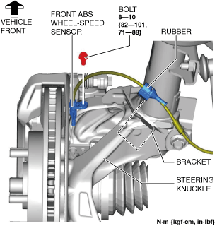
3.Disconnect the front ABS wheel-speed sensor wiring harness on the steering knuckle and set it aside so that it does not interfere with the servicing.
4.Remove the tunnel cover. (See EXHAUST SYSTEM REMOVAL/INSTALLATION [SKYACTIV-G (WITHOUT CYLINDER DEACTIVATION (US))].) (See EXHAUST SYSTEM REMOVAL/INSTALLATION [SKYACTIV-G (WITH CYLINDER DEACTIVATION (US))].)
5.Remove the following parts.
- (1)Front under cover No.1 (See FRONT UNDER COVER No.1 REMOVAL/INSTALLATION.)
- (2)Front under cover No.2 (See FRONT UNDER COVER No.2 REMOVAL/INSTALLATION.)
6. Disconnect the tie-rod end from the steering knuckle. (See TIE-ROD END REPLACEMENT.)
7.Disconnect the front stabilizer control link (front stabilizer side).
ac8wzw00001906
|
8.Disconnect the front lower arm ball joint from the steering knuckle. (See FRONT LOWER ARM REMOVAL/INSTALLATION [(US)].)
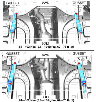
9.Remove the gusset.
am3zzw00031427
|
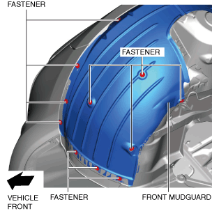
10.Remove the fastener shown in the figure and slightly bend back the front mudguard.
am3zzw00023028
|
11.Remove the front deflector. (See DEFLECTOR REMOVAL/INSTALLATION.)
12.Remove the front splash shield. (See SPLASH SHIELD REMOVAL/INSTALLATION.)
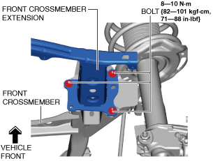
13.Disconnect the front crossmember extension.
am3zzw00023030
|
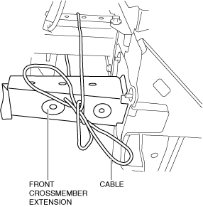
14.Suspend the front crossmember extension using a cable.
am3zzw00023031
|
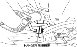
15.Disconnect the hanger rubber from the front crossmember and set it aside.
ac8wzw00001908
|
16.Remove the joint cover. (See STEERING WHEEL AND COLUMN REMOVAL/INSTALLATION [(US)].)
17.Disconnect the intermediate shaft from the steering gear and linkage. (See STEERING WHEEL AND COLUMN REMOVAL/INSTALLATION [(US)].)
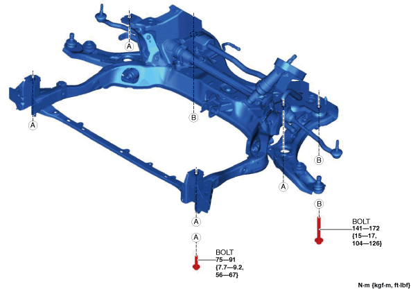
18.Remove the bolt shown in the figure. (See No.1 Engine Mount Rubber, Front Crossmember Component Installation Note.)
am3zzw00031428
|
19.Remove the front crossmember component. (See Front Crossmember Component Removal Note.) (See No.1 Engine Mount Rubber, Front Crossmember Component Installation Note.)
am3zzw00023032
|
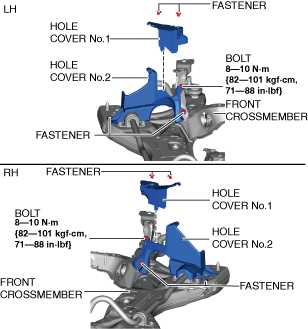
20.Remove the hole cover No.1 and hole cover No.2.
am3zzw00027646
|
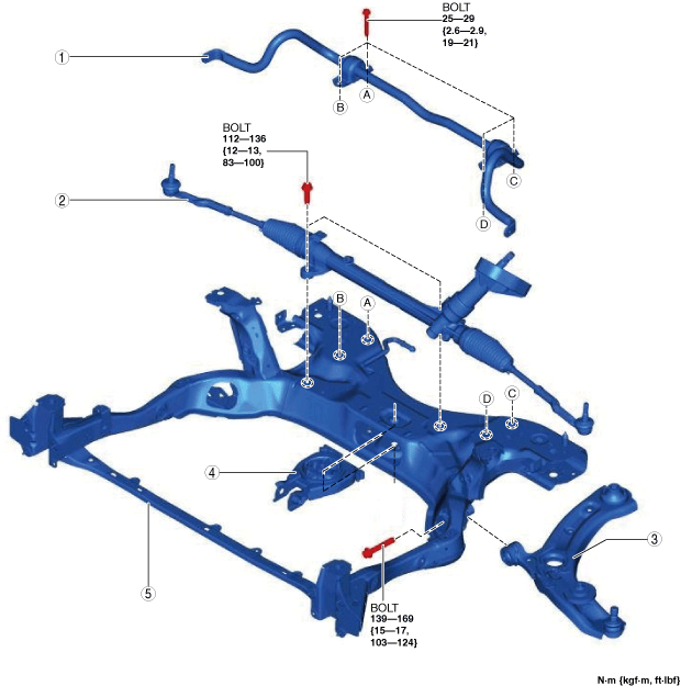
21.Remove in the order shown in the figure.
22.Install in the reverse order of removal. (See Suspension Links Installation Note.)
23.If the front crossmember is replaced, inspect the wheel alignment and adjust it if necessary. (See FRONT WHEEL ALIGNMENT [(US)].)
am3zzw00032540
|
|
1
|
Front stabilizer component
|
|
2
|
Steering gear and linkage
|
|
3
|
Front lower arm
|
|
4
|
No.1 engine mount rubber
|
|
5
|
Front crossmember
|
Front Crossmember Component Removal Note
-
Warning
-
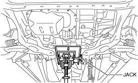
• Always verify that the front crossmember component is securely supported by a jack. If the front crossmember component falls off, it can cause serious injury or death, and damage to the vehicle.
1.Support the front crossmember component using a jack.
ac8wzw00001912
|
2.Remove the installation bolts of the front crossmember component.
3.Move the front crossmember extension and slowly lower the transmission jack.
4.Remove the front crossmember, front stabilizer, front lower arm, and the steering gear and linkage as a single unit.
Suspension Links Installation Note
1.When installing the joint sections with rubber bushings, perform the following procedures.
- (1)Temporarily tighten the bolt with the vehicle lifted up.
- (2)Lower the vehicle to the ground and tighten the bolt to the specified torque.
No.1 Engine Mount Rubber, Front Crossmember Component Installation Note
-
Caution
-
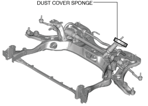
• When installing the front crossmember component to the vehicle, if the dust boots are not assembled to the body side correctly water and foreign matter could penetrate the vehicle interior. Be careful not to allow the sponge part of the dust boot to become pinched in the installation area on the body side or become creased by contact.
 am3zzw00023035
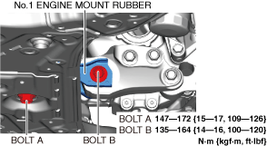
1.Temporarily tighten bolt A shown in the figure.
am3zzw00032541
|
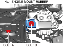
2.Temporarily tighten bolt B shown in the figure.
3.Tighten bolt A.
4.Tighten bolt B.