EXHAUST SYSTEM REMOVAL/INSTALLATION [SKYACTIV-G (WITHOUT CYLINDER DEACTIVATION (US))]
EXHAUST SYSTEM REMOVAL/INSTALLATION [SKYACTIV-G (WITHOUT CYLINDER DEACTIVATION (US))]
SM2565760
id0115u0800200
Replacement Part
|
Gasket
Quantity: 1
Location of use: Main silencer
|
Nut
Quantity: 4
Location of use: TWC
|
Exhaust manifold gasket
Quantity: 1
Location of use: Exhaust manifold
|
|
Gasket
Quantity: 1
Location of use: Exhaust manifold
|
Nut
Quantity: 5
Location of use: Exhaust manifold (WU-TWC)
|
—
|
-
Warning
-
• A hot engine and exhaust system can cause severe burns. Turn off the engine and wait until they are cool before removing the exhaust system.
1.Disconnect the negative battery terminal. (See NEGATIVE BATTERY TERMINAL DISCONNECTION/CONNECTION [(US)].)
2.Remove in the order indicated in the table.
3.Remove the insulator. (See Exhaust System Insulator Removal/Installation.)
4.Install in the reverse order of removal.
Step 1
am3zzw00032234
|

|
1
|
Main silencer
|
|
2
|
Tunnel cover
|
|
3
|
Brace bar
(See Brace Bar Installation Note.)
|
|
4
|
Tunnel member
|
|
5
|
Connector
|
|
6
|
TWC component
(See TWC component Removal Note.)
|
|
7
|
HO2S
|
|
8
|
TWC
|
Step 2
am3zzw00021200
|
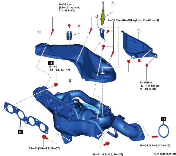
|
1
|
A/F sensor
|
|
2
|
Clip
|
|
3
|
Insulator
|
|
4
|
Exhaust manifold insulator
|
|
5
|
Exhaust manifold (WU-TWC)
|
|
6
|
Exhaust manifold gasket
|
Exhaust System Insulator Removal/Installation
1.Remove the floor under cover No.1 (RH). (See FLOOR UNDER COVER REMOVAL/INSTALLATION.)
2.Remove the floor under cover No.2. (See FLOOR UNDER COVER REMOVAL/INSTALLATION.)
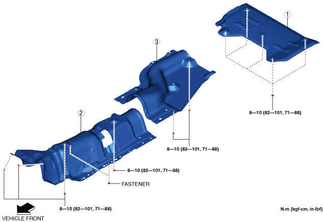
3.Remove the exhaust system insulator in the order shown in the figure.
4.Install in the reverse order of removal.
am3zzw00021232
|
|
1
|
Insulator (rear)
|
|
2
|
Insulator (front)
|
|
3
|
Insulator (middle)
|
TWC component Removal Note
1.Remove the floor under cover No.1 (LH). (See FLOOR UNDER COVER REMOVAL/INSTALLATION.)
2.Remove the TWC component.
Exhaust Manifold Insulator Removal Note
1.Remove the insulator as shown in the figure.
am3zzw00032141
|
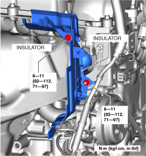
2.Remove the exhaust manifold insulator.
Exhaust Manifold Removal Note
-
Note
-
• When removing the exhaust manifold, the bracket installed under the exhaust manifold does not have to be removed. Remove the exhaust manifold with the bracket installed.
1.Remove the front crossmember. (See FRONT CROSSMEMBER REMOVAL/INSTALLATION [(US)].)
2.Remove the exhaust manifold.
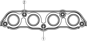
Exhaust Manifold Installation Note
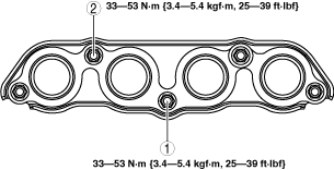
1.Temporarily tighten the exhaust manifold installation nuts (1) and (2) shown in the figure by hand.
ac5uuw00002679
|
2.Tighten the exhaust manifold installation nuts (1) and (2) shown in the figure.
am3zzw00032166
|
3.Temporarily tighten the exhaust manifold installation nuts (3) to (5) shown in the figure by hand.
ac5wzw00002715
|
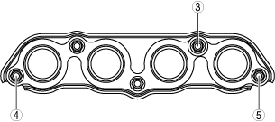
4.Tighten the exhaust manifold installation nuts (3) to (5) shown in the figure.
5.Tighten the exhaust manifold installation nuts (1) and (2) shown in the figure.
6.Temporarily tighten the bolts (6) and (7) shown in the figure.
ac5uuw00009265
|
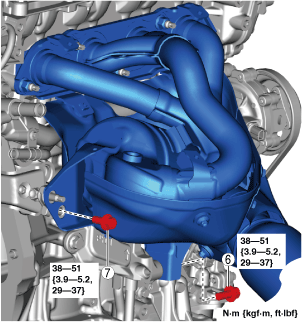
7.Tighten the bolt (6) shown in the figure.
8.Tighten the bolt (7) shown in the figure.
Exhaust Manifold Insulator Installation Note
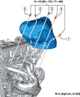
1.Temporarily tighten the exhaust manifold insulator.
2.Tighten the exhaust manifold insulator in the order shown in the figure.
am3zzw00029132
|
Insulator (middle) installation note
1.Align the stud bolts shown in the figure with the insulator (middle) and install.
am3zzw00021202
|
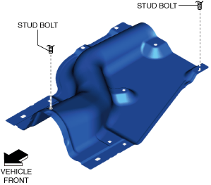
2.Tighten the nuts to the specified torque.
Insulator (front) installation note
1.Align the stud bolts shown in the figure with the insulator (front) and install.
am3zzw00021201
|
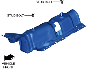
2.Install the fasteners.
3.Tighten the nuts to the specified torque.
Insulator (rear) installation note
1.Align the stud bolt shown in the figure with the insulator (rear) and install.
am3zzw00021203
|
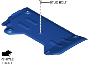
2.Tighten the nuts to the specified torque.
Tunnel Member Installation Note
1.Tighten bolt A shown in the figure to the specified torque.
am3zzw00021204
|
2.Tighten bolt B shown in the figure to the specified torque.
3.Tighten the remaining bolts and nuts to the specified torque.
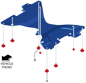
Brace Bar Installation Note
1.Tighten bolt A shown in the figure to the specified torque.
am3zzw00021205
|
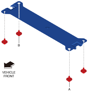
2.Tighten bolt B shown in the figure to the specified torque.
3.Tighten the remaining bolts to the specified torque.
Tunnel cover Installation Note
1.Align the stud bolt shown in the figure with the tunnel cover and install.
am3zzw00021233
|
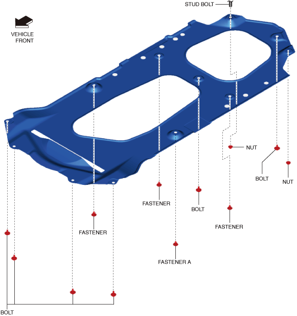
2.Install fastener A shown in the figure.
3.Install the remaining fasteners.
4.Tighten the bolts shown in the figure to the specified torque.
5.Tighten the nuts shown in the figure to the specified torque.