STEERING GEAR AND LINKAGE DISASSEMBLY [(US)]
STEERING GEAR AND LINKAGE DISASSEMBLY [(US)]
SM2335538
id0613008018x1
Special service tool (SST)
|
49 JP02 001
Adjustable wrench
|
 |
-
Caution
-
• Performing the following procedures could cause an open circuit in the front ABS wheel-speed sensor wiring harness if it is pulled by mistake. Before servicing, disconnect the front ABS wheel-speed sensor and set it aside so that the wiring harness will not be pulled by mistake.• If the steering wheel rotates after the steering shaft and the steering gear and linkage are disconnected, the internal parts of the clock spring could be damaged. Disconnect the steering shaft and then secure the steering wheel with tape or cable so that it does not rotate.• Do not allow the dust boot of the front stabilizer control link to touch the body, the front shock absorber and coil spring, and the hand tool. Otherwise, the dust boot of the front stabilizer control link could be damaged.• If using a vise, secure the steering gear to the vise using a copper plate or cloth to prevent steering gear damage.
1.Remove the wheel and tire. (See WHEEL AND TIRE REMOVAL/INSTALLATION.)
2.Disconnect the rubber from the bracket.
am3zzw00023145
|
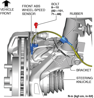
3.Disconnect the front ABS wheel-speed sensor wiring harness on the steering knuckle and set it aside so that it does not interfere with the servicing.
4.Remove the tunnel cover. (See EXHAUST SYSTEM REMOVAL/INSTALLATION [SKYACTIV-G (WITHOUT CYLINDER DEACTIVATION (US))].) (See EXHAUST SYSTEM REMOVAL/INSTALLATION [SKYACTIV-G (WITH CYLINDER DEACTIVATION (US))].)
5.Remove the following parts.
- (1)Front under cover No.1 (See FRONT UNDER COVER No.1 REMOVAL/INSTALLATION.)
- (2)Front under cover No.2 (See FRONT UNDER COVER No.2 REMOVAL/INSTALLATION.)
6. Disconnect the tie-rod end from the steering knuckle. (See TIE-ROD END REPLACEMENT.)
7.Disconnect the front lower arm ball joint from the steering knuckle. (See FRONT LOWER ARM REMOVAL/INSTALLATION [(US)].)
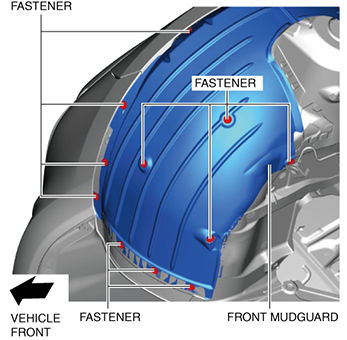
8.Remove the fastener shown in the figure and slightly bend back the front mudguard.
am3zzw00023146
|
9.Remove the front deflector. (See DEFLECTOR REMOVAL/INSTALLATION.)
10.Remove the front splash shield. (See SPLASH SHIELD REMOVAL/INSTALLATION.)
11.Remove the joint cover. (See INTERMEDIATE SHAFT REMOVAL/INSTALLATION [(US)].)
12.Disconnect the intermediate shaft from the steering gear and linkage. (See INTERMEDIATE SHAFT REMOVAL/INSTALLATION [(US)].)
13.Remove the front crossmember component. (See FRONT CROSSMEMBER REMOVAL/INSTALLATION [(US)].)
14.Remove the hole cover No.1 and hole cover No.2. (See FRONT CROSSMEMBER REMOVAL/INSTALLATION [(US)].)
15.Remove the steering gear and linkage from the front crossmember component. (See STEERING GEAR AND LINKAGE REMOVAL/INSTALLATION [(US)].)
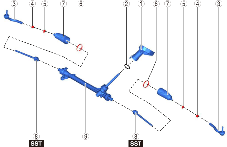
16.Disassemble in the order shown in the figure.
am3zzw00023147
|
|
1
|
Dust cover
|
|
2
|
O-ring
|
|
3
|
Tie-rod end
(See Tie-rod End Disassembly Note.)
|
|
4
|
Locknut
|
|
5
|
Boot clamp
|
|
6
|
Boot band
(See Boot Band Disassembly Note.)
|
|
7
|
Boot
|
|
8
|
Tie rod
(See Tie Rod Disassembly Note.)
|
|
9
|
Steering gear
|
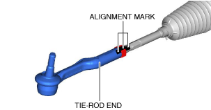
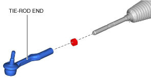
Tie-rod End Disassembly Note
1.Place alignment marks as shown in the figure for reference in assembly.
am3zzw00023148
|
2.Remove the tie-rod end.
am3zzw00023149
|
Boot Band Disassembly Note
1.Insert a flathead screwdriver into the crimped part of the boot clamp, expand the crimped part, and then remove the boot clamp as shown in the figure.
ac5wzw00001035
|
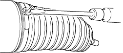
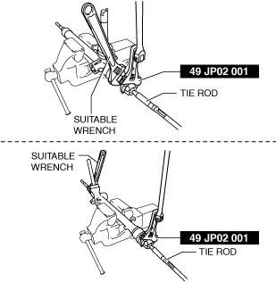
Tie Rod Disassembly Note
1.Lock the steering gear against rotation using a wrench and remove the tie rod using the SST.
am3zzw00033060
|