STEERING WHEEL AND COLUMN REMOVAL/INSTALLATION [(US)]
STEERING WHEEL AND COLUMN REMOVAL/INSTALLATION [(US)]
SM2335534
id0613008014x1
Replacement part
|
Lockbolt
Quantity: 1
Location of use: Steering wheel
|
Joint bolt
Quantity: 1
Location of use: Intermediate shaft (upper side)
|
Joint bolt
Quantity: 1
Location of use: Intermediate shaft (lower side)
|
-
Warning
-
• Handling the driver-side air bag module improperly can accidentally operate (deploy) the air bag module, which may seriously injure you. Read the air bag system service warnings and cautions before handling the driver-side air bag module. (See AIR BAG SYSTEM SERVICE WARNINGS [STANDARD DEPLOYMENT CONTROL SYSTEM – MEXICO SPEC.].) (See AIR BAG SYSTEM SERVICE CAUTIONS [STANDARD DEPLOYMENT CONTROL SYSTEM – MEXICO SPEC.].) (See AIR BAG SYSTEM SERVICE WARNINGS [TWO-STEP DEPLOYMENT CONTROL SYSTEM – US/CANADA SPEC.].) (See AIR BAG SYSTEM SERVICE CAUTIONS [TWO-STEP DEPLOYMENT CONTROL SYSTEM – US/CANADA SPEC.].)• If the steering mechanism is turned from lock to lock continuously or the steering rack terminal limit is reached repeatedly, such high-load steering action increases the temperature of the steering column (to approx. 85 °C {185 °F}), causing severe burns. Be careful when handling the steering column.• If the steering column is dropped, the EPS control module could be damaged internally causing the steering mechanism to become inoperative, which could result in an unexpected accident. Always replace a steering column which has been received an impact.
-
Caution
-
• When replacing the EPS CM, perform the configuration to assure that the system operates correctly. (See CONFIGURATION.)• If the steering column is dropped it could result in internal damage to the EPS CM, therefore be careful not to drop it. If the EPS CM receives an impact, replace it.• If the steering column is stored in a humid place, the EPS system may not operate properly when installed to the vehicle. Store the steering column in a suitable place.• Because the weight of the steering column is approx. 10 kg {22 lb}, it may fall off during servicing and be damaged. Be careful when handling the steering column.• If the intermediate shaft is connected to the steering gear (pinion) before installing the steering column to the dashboard member, the weight of the steering column could cause damage to the intermediate shaft slider/bush/yoke. Always perform the procedure according to the workshop manual.• The universal joint could be damaged if subjected to an impact when the intermediate shaft (pinion) is disconnected. Perform the servicing carefully avoiding impact when disconnecting the intermediate shaft from the steering gear (pinion).• When handling the steering column, do not release the adjuster lever lock except when the steering column is securely assembled to the dashboard member. Otherwise, it could damage the steering column and the other parts.• A new steering column is shipped with it set to the position for delivery. Maintain this condition until the steering column is completely installed to the dashboard member so as to avoid damage during transportation and installation.• When removing/installing the steering column, keep the wiring harness away from the steering column installation area so as to prevent the steering column from being caught in the wiring harness and damaged.
-
Note
-
• If the vehicle is driven in a straight line at a vehicle speed of approx. 10 km/h {6.2 mph} or more, the EPS CM detects the steering angle neutral position automatically. Until the self-learning of the steering angle neutral position is finished, the EPS CM performs assist control based on the steering angle recognized when the ignition is switched ON (engine off or on).• When installing the replacement part, do not rotate the steering shaft until the installation is completed.• In order to completely interrupt the EPS system power supply, do not disconnect the battery within 60 s after the ignition switch is turned off.• Do not replace the steering column (EPS system) with that of another vehicle even if they are the same model.• Before connecting the EPS CM connector, remove the fuse or disconnect the battery to interrupt the power supply completely.
1.Disconnect the negative battery terminal and wait for 1 min or more. (See NEGATIVE BATTERY TERMINAL DISCONNECTION/CONNECTION [(US)].)
2.Remove the driver-side air bag module. (See DRIVER-SIDE AIR BAG MODULE REMOVAL [STANDARD DEPLOYMENT CONTROL SYSTEM – MEXICO SPEC.].) (See DRIVER-SIDE AIR BAG MODULE INSTALLATION [STANDARD DEPLOYMENT CONTROL SYSTEM – MEXICO SPEC.].) (See DRIVER-SIDE AIR BAG MODULE REMOVAL [TWO-STEP DEPLOYMENT CONTROL SYSTEM – US/CANADA SPEC.].) (See DRIVER-SIDE AIR BAG MODULE INSTALLATION [TWO-STEP DEPLOYMENT CONTROL SYSTEM – US/CANADA SPEC.].)
3.Straighten the steering wheel.
4.Disconnect the heated steering wheel control unit connector. (With heated steering wheel system)
am3zzw00023125
|
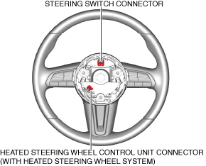
5.Disconnect the steering switch connector.
6.Remove the lockbolt.
am3zzw00023126
|
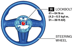
7.Remove the steering wheel.
-
Caution
-
• Do not remove the steering wheel using a hammer so as to prevent damaging the steering column.
8.Remove the following parts.
- (1)Driver-side front scuff plate (See FRONT SCUFF PLATE REMOVAL/INSTALLATION.)
- (2)Driver-side front side trim (See FRONT SIDE TRIM REMOVAL/INSTALLATION.)
- (3)Driver-side decoration panel (See DECORATION PANEL REMOVAL/INSTALLATION.)
- (4)Passenger-side decoration panel (See DECORATION PANEL REMOVAL/INSTALLATION.)
- (5)Hood release lever (See HOOD RELEASE LEVER AND RELEASE CABLE REMOVAL/INSTALLATION [(US)].)
- (6)Driver-side lower panel (See LOWER PANEL REMOVAL/INSTALLATION [(US)].)
9.Remove the knee air bag.(See KNEE AIR BAG MODULE REMOVAL/INSTALLATION [STANDARD DEPLOYMENT CONTROL SYSTEM – MEXICO SPEC.].) (See KNEE AIR BAG MODULE REMOVAL/INSTALLATION [TWO-STEP DEPLOYMENT CONTROL SYSTEM – US/CANADA SPEC.].)
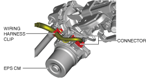
10.Disconnect the wiring harness clip and connectors shown in the figure.
am3zzw00033057
|
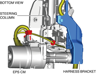
11.Remove the harness bracket from the steering column and set it aside so that it does not interfere with the servicing.
am3zzw00023128
|
12.Remove the following parts.
- (1)Column cover (See COLUMN COVER REMOVAL/INSTALLATION.)
- (2)Clock spring (See CLOCK SPRING REMOVAL/INSTALLATION [STANDARD DEPLOYMENT CONTROL SYSTEM – MEXICO SPEC.].) (See CLOCK SPRING REMOVAL/INSTALLATION [TWO-STEP DEPLOYMENT CONTROL SYSTEM – US/CANADA SPEC.].)
- (3)Light switch (See LIGHT SWITCH REMOVAL/INSTALLATION [(US)].)
- (4)Wiper and washer switch (See WIPER AND WASHER SWITCH REMOVAL/INSTALLATION [(US)].)
13.Remove in the order shown in the figure.
14.Install in the reverse order of removal.
15.If the EPS CM is replaced, perform the following procedure.
- (1)Complete the EPS CM automatic configuration using the following procedure.
-
- 1)Switch the ignition ON (engine off or on) and wait for 1 min or more.
- 2)Switch the ignition OFF and wait for 3 s or more.
- 3)Switch the ignition ON (engine off or on) again.
- (2)Clear the DTC. (See CLEARING DTC.)
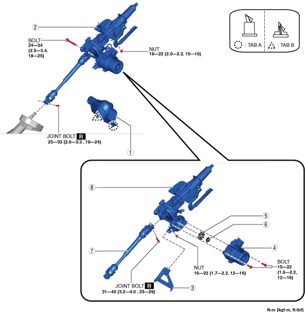
am3zzw00035287
|
|
1
|
Joint cover
|
|
2
|
Steering column component
|
|
3
|
bracket (MTX)
|
|
4
|
EPS CM
(See EPS CM Removal Note.)
|
|
5
|
Rubber
|
|
6
|
Spacer
|
|
7
|
Intermediate shaft
|
|
8
|
Steering column
|
Steering Column Component Removal Note
-
Caution
-
• Always lock the adjuster lever. Otherwise, the steering column component could be damaged. In addition, do not release the lock of the adjuster lever until the steering column component installation is completed.• When removing the steering column component, follow the procedure. Otherwise, it could damage the intermediate shaft.
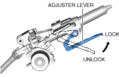
1.Lock the adjuster lever.
am3zzw00023130
|
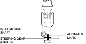
2.Place alignment marks on the steering gear (pinion) and intermediate shaft as shown in the figure.
ac8wzw00001495
|
3.Remove the joint bolt.
4.Disconnect the intermediate shaft from the steering gear (pinion).
5.Remove the nuts, then remove the steering column component from the dashboard member.
EPS CM Removal Note
1.Disconnect the torque sensor connector (EPS CM side).
am3zzw00023131
|
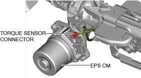
2.Remove the EPS CM.
-
Warning
-
• The internal parts of the EPS CM or the motor could be damaged if the EPS CM is hit. Be careful not to hit the EPS CM. Replace the EPS CM if it gets hit.• Be careful that liquid or foreign matter does not get inside the EPS CM and the steering column. Otherwise, the EPS CM motor could be damaged.
Intermediate Shaft Removal Note
1.Lock the adjuster lever.
am3zzw00023130
|
2.Place an alignment mark across the break between the steering column and the yoke for the intermediate shaft as shown in the figure.
ac8wzw00001497
|
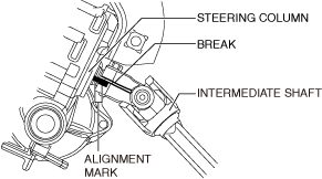
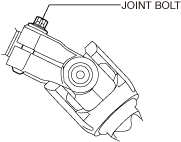
3.Remove the joint bolt.
am3zzw00023132
|
4.Remove the intermediate shaft from the steering column.
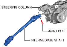
Intermediate Shaft Installation Note
1.Align the intermediate shaft with the alignment marks on the steering column made before removing the intermediate shaft and install the intermediate shaft.
ac8wzw00001497
|
-
Note
-
• When replacing the steering column with a new one, place an alignment mark on the new part in the same position as the removed steering column.
2.Install a new joint bolt.
am3zzw00023133
|
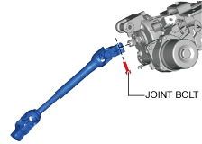
3.Verify that the joint bolt flange is seated correctly.
am3zzw00031472
|
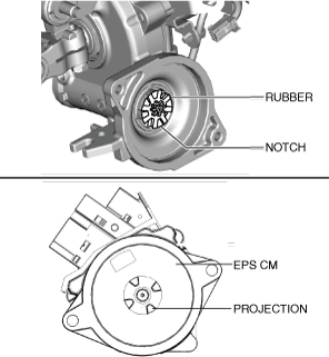
Spacer, Rubber, EPS CM Installation Note
1.Install the spacer and rubber to the steering column.
2.Install the EPS CM so that the projection of the EPS CM (rotor) is engaged with the notch in the rubber.
am3zzw00023134
|
-
Caution
-
• When assembling the EPS CM, be careful not to pinch the wiring harness of the torque sensor. If the wiring harness of the torque sensor is damaged, replace the steering column component.
-
Note
-
• If the projection of the EPS CM (rotor) is not engaged with the notch in the rubber, adjust the position of the EPS CM projection (rotor).
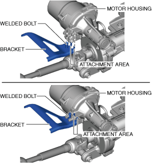
Bracket Installation Note (MTX)
1.While inserting the attachment areas of the bracket into the motor housing holes, insert the welded bolt of the bracket into the concavity in the motor housing.
am3zzw00023135
|
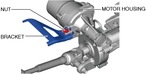
2.With the installation surface of the bracket contacting the motor housing, tighten the installation nut to the specified torque.
am3zzw00031473
|
Steering Column Component Installation Note
-
Caution
-
• Always lock the adjuster lever. Otherwise, the steering column component could be damaged. In addition, do not release the lock of the adjuster lever until the steering column component installation is completed.• When installing the steering column component, follow the procedure. Otherwise, it could damage the intermediate shaft.
1.Verify that the adjust lever of the steering column is locked.
am3zzw00023130
|
2.Temporarily install the steering column component to the dashboard member using bolt and nuts.
am3zzw00023137
|
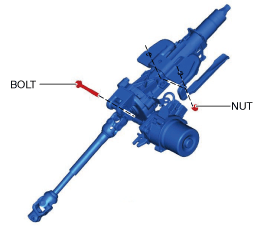
3.Tighten the nuts.
4.Tighten the bolt.
5.Align the intermediate shaft with the alignment marks on the intermediate shaft and steering gear (pinion) made before removing the intermediate shaft and install the intermediate shaft.
ac8wzw00001495
|
6.Insert the intermediate shaft into the steering gear (pinion) to the position shown in the figure and tighten it using a new joint bolt.
am3zzw00031475
|
