COLUMN COVER REMOVAL/INSTALLATION
COLUMN COVER REMOVAL/INSTALLATION
SM2336530
id091700800800
Upper Column Cover
1.Disconnect the negative battery terminal. (See NEGATIVE BATTERY TERMINAL DISCONNECTION/CONNECTION [(US)].)
2.Remove the following parts:
- (1)Shift lever knob (MTX) (See SHIFT LEVER REMOVAL/INSTALLATION [C66M-R].)
- (2)Selector lever knob (ATX) (See SELECTOR LEVER COMPONENT REMOVAL/INSTALLATION.)
- (3)Shift panel (See SHIFT PANEL REMOVAL/INSTALLATION.)
- (4)Front console box (See FRONT CONSOLE BOX REMOVAL/INSTALLATION.)
- (5)Cup holder (See CUP HOLDER REMOVAL/INSTALLATION.)
- (6)Side wall (See SIDE WALL REMOVAL/INSTALLATION.)
- (7)Rear console (See REAR CONSOLE REMOVAL/INSTALLATION [(US)].)
- (8)Driver-side front scuff plate (See FRONT SCUFF PLATE REMOVAL/INSTALLATION.)
- (9)Driver-side front side trim (See FRONT SIDE TRIM REMOVAL/INSTALLATION.)
- (10)Driver-side decoration panel (See DECORATION PANEL REMOVAL/INSTALLATION.)
- (11)Passenger-side decoration panel (See DECORATION PANEL REMOVAL/INSTALLATION.)
- (12)Hood release lever (See HOOD RELEASE LEVER AND RELEASE CABLE REMOVAL/INSTALLATION [(US)].)
- (13)Driver-side lower panel (See LOWER PANEL REMOVAL/INSTALLATION [(US)].)
- (14)Driver-side knee air bag module (See KNEE AIR BAG MODULE REMOVAL/INSTALLATION [STANDARD DEPLOYMENT CONTROL SYSTEM – MEXICO SPEC.].) (See KNEE AIR BAG MODULE REMOVAL/INSTALLATION [TWO-STEP DEPLOYMENT CONTROL SYSTEM – US/CANADA SPEC.].)
- (15)Center lower panel (See LOWER PANEL REMOVAL/INSTALLATION [(US)].)
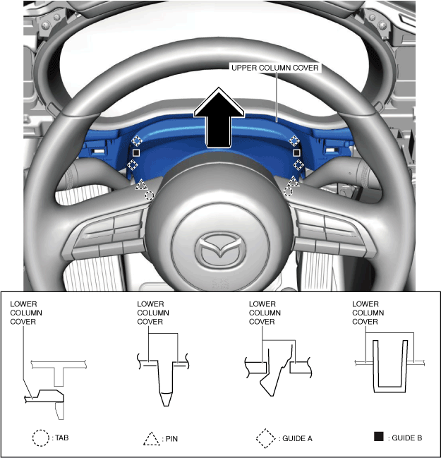
3.Move the upper column cover in the direction of the arrow, and detach the pins, tabs, guides A and B from the lower column cover.
am3zzw00024062
|
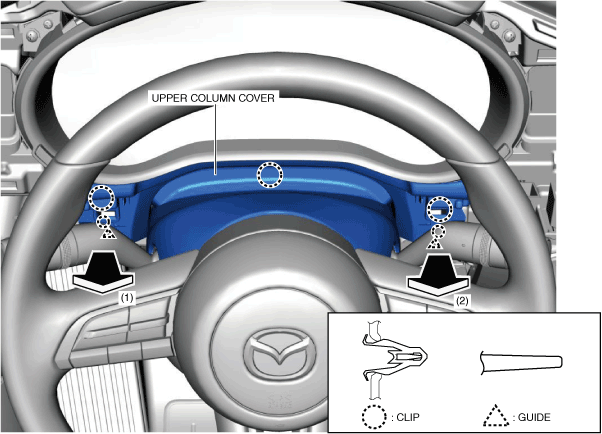
4.Move the upper column cover in the order of arrows (1) and (2) shown in the figure, and remove it while detaching the clips and guides.
am3zzw00021793
|
5.Install in the reverse order of removal.
Lower Column Cover
1.Disconnect the negative battery terminal. (See NEGATIVE BATTERY TERMINAL DISCONNECTION/CONNECTION [(US)].)
2.Remove the following parts:
- (1)Shift lever knob (MTX) (See SHIFT LEVER REMOVAL/INSTALLATION [C66M-R].)
- (2)Selector lever knob (ATX) (See SELECTOR LEVER COMPONENT REMOVAL/INSTALLATION.)
- (3)Shift panel (See SHIFT PANEL REMOVAL/INSTALLATION.)
- (4)Front console box (See FRONT CONSOLE BOX REMOVAL/INSTALLATION.)
- (5)Cup holder (See CUP HOLDER REMOVAL/INSTALLATION.)
- (6)Side wall (See SIDE WALL REMOVAL/INSTALLATION.)
- (7)Rear console (See REAR CONSOLE REMOVAL/INSTALLATION [(US)].)
- (8)Driver-side front scuff plate (See FRONT SCUFF PLATE REMOVAL/INSTALLATION.)
- (9)Driver-side front side trim (See FRONT SIDE TRIM REMOVAL/INSTALLATION.)
- (10)Driver-side decoration panel (See DECORATION PANEL REMOVAL/INSTALLATION.)
- (11)Passenger-side decoration panel (See DECORATION PANEL REMOVAL/INSTALLATION.)
- (12)Hood release lever (See HOOD RELEASE LEVER AND RELEASE CABLE REMOVAL/INSTALLATION [(US)].)
- (13)Driver-side lower panel (See LOWER PANEL REMOVAL/INSTALLATION [(US)].)
- (14)Driver-side knee air bag module (See KNEE AIR BAG MODULE REMOVAL/INSTALLATION [STANDARD DEPLOYMENT CONTROL SYSTEM – MEXICO SPEC.].) (See KNEE AIR BAG MODULE REMOVAL/INSTALLATION [TWO-STEP DEPLOYMENT CONTROL SYSTEM – US/CANADA SPEC.].)
- (15)Center lower panel (See LOWER PANEL REMOVAL/INSTALLATION [(US)].)
- (16)Upper column cover (See Upper Column Cover.)
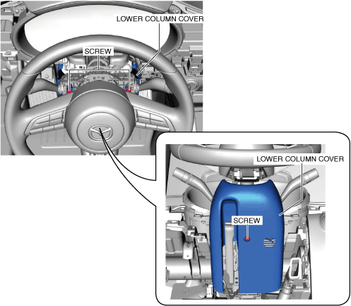
3.Remove the screws.
am3zzw00021794
|
4.Lower the adjusting lever to the bottommost position.
am3zzw00021795
|
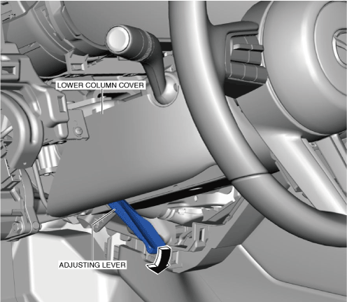
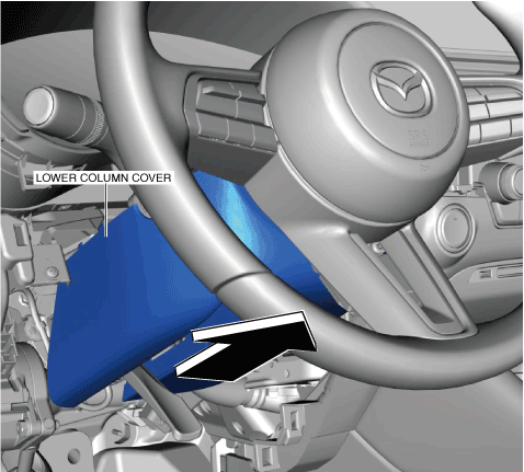
5.Remove the lower column cover in the direction of the arrow shown in the figure.
am3zzw00021796
|
6.Disconnect the notification and warning speaker connector. (with notification and warning speaker)
7.Install in the reverse order of removal.
-
Note
-
• When replacing the lower column cover, remove the notification and warning speaker (front). (with notification and warning speaker) (See NOTIFICATION AND WARNING SPEAKER REMOVAL/INSTALLATION.)