CLOCK SPRING REMOVAL/INSTALLATION [TWO-STEP DEPLOYMENT CONTROL SYSTEM – US/CANADA SPEC.]
CLOCK SPRING REMOVAL/INSTALLATION [TWO-STEP DEPLOYMENT CONTROL SYSTEM – US/CANADA SPEC.]
SM2335915
id0810b4802000
-
Warning
-
• Handling the driver-side air bag module improperly can accidentally operate (deploy) the air bag module, which may seriously injure you. Read the air bag system service warnings and cautions before handling the driver-side air bag module. (See AIR BAG SYSTEM SERVICE WARNINGS [TWO-STEP DEPLOYMENT CONTROL SYSTEM – US/CANADA SPEC.].) (See AIR BAG SYSTEM SERVICE CAUTIONS [TWO-STEP DEPLOYMENT CONTROL SYSTEM – US/CANADA SPEC.].)
1.Set the front wheels straight ahead.
2.Switch the ignition off.
3.Disconnect the negative battery terminal and wait for 1 min or more. (See NEGATIVE BATTERY TERMINAL DISCONNECTION/CONNECTION [(US)].)
4.Remove the following parts:
- (1)Driver-side air bag module (See DRIVER-SIDE AIR BAG MODULE REMOVAL [TWO-STEP DEPLOYMENT CONTROL SYSTEM – US/CANADA SPEC.].)(See DRIVER-SIDE AIR BAG MODULE INSTALLATION [TWO-STEP DEPLOYMENT CONTROL SYSTEM – US/CANADA SPEC.].)
- (2)Steering wheel (See STEERING WHEEL AND COLUMN REMOVAL/INSTALLATION [(US)].)
- (3)Column cover (See COLUMN COVER REMOVAL/INSTALLATION.)
5.Disconnect the clock spring connector A. (See Clock Spring Connector A Disconnect Note.)
am3zzw00021550
|
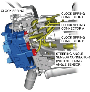
6.Disconnect the clock spring connector B.
7.Disconnect the clock spring connector C.
8.Disconnect the steering angle sensor connector. (with steering angle sensor)
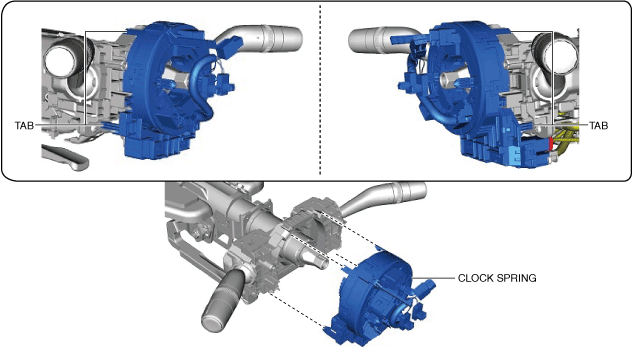
9.Remove the tabs as shown in the figure and remove the clock spring.
am3zzw00021551
|
10.Install in the reverse order of removal. (See Clock Spring Installation Note.)
11.Switch the ignition ON (engine off or on).
12.Verify that the air bag/seat belt pre-tensioner system warning light illuminates for approx. 6 s and turns off.
-
• If the air bag/seat belt pre-tensioner system warning light does not operate normally, refer to the on-board diagnostic system (air bag system) and perform inspection of the system. (See DTC INSPECTION.)
Clock Spring Connector A Disconnect Note
1.Pull out the clock spring connector A lock lever in the direction of arrow (1) shown in the figure.
am6zzw00016158
|
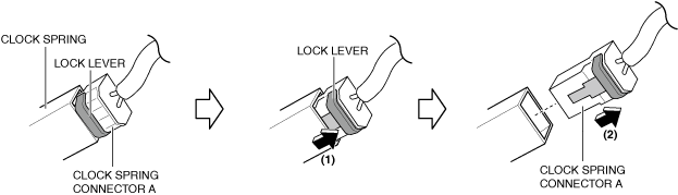
2.Move the clock spring connector A in the direction of arrow (2) shown in the figure to disconnect it.
Clock Spring Installation Note
-
Caution
-
• If the clock spring is not adjusted, the spring wire in the clock spring will break due to overtension when the steering wheel is turned. Always adjust the clock spring after installing it.