EXHAUST SMOKE [SKYACTIV-G]
EXHAUST SMOKE [SKYACTIV-G]
SM2334620
id0103s4890600
|
Troubleshooting item |
Exhaust smoke |
|
|---|---|---|
|
Description
|
• Blue, black, or white smoke from exhaust system.
|
|
|
Possible cause
|
Blue smoke (Burning oil):
• PCV valve malfunction
• Engine internal oil leakage
White smoke (Water in combustion):
• Cooling system malfunction (coolant loss)
• Engine internal coolant leakage
Black smoke (Rich fuel mixture):
• Erratic signal to PCM
• Improper fuel injection timing and amount
• Air cleaner restriction
• Intake-air system is collapsed or restricted
• Leakage at engine intake manifold and/or exhaust manifold
• Inadequate/Excessive fuel pressure
• Ignition system malfunction
• Improper engine compression
• Improper intake valve timing
• Improper exhaust valve timing
• Injector driver (built-into PCM) malfunction
|
|
|
Possible cause
|
|
|
 |
||
 |
||
 |
||
-
Caution
-
• Verify the malfunction symptom according to not only the PID value but also the symptom troubleshooting.
Related PIDs
|
PIDs |
Reference |
|---|---|
|
APP1
|
|
|
APP2
|
|
|
ECT
|
|
|
ECT_VOLT
|
|
|
ECT2
|
|
|
ECT2_VOLT
|
|
|
FUEL_PRES
|
|
|
IAT
|
|
|
LOAD_CALC
|
|
|
LONG_FUEL_TRIM
|
|
|
MAF
|
|
|
MAP
|
|
|
MAP_VOLT
|
|
|
A/F_SEN_CUR
|
|
|
HO2S_OUT_VOLT
|
|
|
ENG_RPM
|
|
|
SHRT_FUEL_TRIM
|
|
|
TP_RELAT
|
|
|
VSS
|
Diagnostic Procedure
|
Step |
Inspection |
Results |
Action |
|---|---|---|---|
|
1
|
VERIFY EXHAUST COLOR
• What color is smoke coming from the exhaust system?
|
Blue
|
Burning oil is indicated.
• Go to the next step.
|
|
White
|
Water in combustion is indicated.
• Go to Step 4.
|
||
|
Black
|
Rich fuel mixture is indicated.
• Go to Step 5.
|
||
|
2
|
INSPECT PCV VALVE FOR MALFUNCTION
• Inspect the applicable part. (See POSITIVE CRANKCASE VENTILATION (PCV) VALVE INSPECTION [SKYACTIV-G (WITH CYLINDER DEACTIVATION (US))].) (See POSITIVE CRANKCASE VENTILATION (PCV) VALVE INSPECTION [SKYACTIV-G (WITHOUT CYLINDER DEACTIVATION (US))].)
• Is the part normal?
|
Yes
|
Go to the next step.
|
|
No
|
Repair or replace the malfunctioning location and perform the repair completion verification.
|
||
|
3
|
INSPECT ENGINE INTERNAL PARTS
• Inspect for the following engine internal parts:
• Is there any malfunction?
|
Yes
|
Repair or replace the malfunctioning location and perform the repair completion verification.
|
|
No
|
Engine internal parts are normal.
• If other driveability symptoms are present:
|
||
|
4
|
INSPECT ENGINE FOR ENGINE COOLANT LEAKAGE
• Does the cooling system hold the coolant pressure? (See ENGINE COOLANT LEAKAGE INSPECTION [SKYACTIV-G (WITH CYLINDER DEACTIVATION (US))].) (See ENGINE COOLANT LEAKAGE INSPECTION [SKYACTIV-G (WITHOUT CYLINDER DEACTIVATION (US))].)
|
Yes
|
Inspect the following:
• Cylinder head gasket leakage
• Intake manifold gasket leakage
• Cracked or porous engine block
If there is any malfunction:
• Repair or replace the malfunctioning location and perform the repair completion verification.
If there is no malfunction:
• If other driveability symptoms are present:
|
|
No
|
Repair or replace the malfunctioning location and perform the repair completion verification.
|
||
|
5
|
VERIFY CURRENT INPUT SIGNAL STATUS
• Access the following PIDs using the M-MDS: (See PID/DATA MONITOR INSPECTION.)
• Monitor the PIDs under the black smoke appeared engine condition.
• Do the PIDs indicate normal according to engine conditions? (See PID/DATA MONITOR TABLE [PCM (SKYACTIV-G (US))].)
|
Yes
|
Go to the next step.
|
|
No
|
APP1, APP2 PIDs are not as specified:
• Inspect the APP sensor No.1 and No.2. (See ACCELERATOR PEDAL POSITION (APP) SENSOR INSPECTION [SKYACTIV-G (WITH CYLINDER DEACTIVATION (US))].) (See ACCELERATOR PEDAL POSITION (APP) SENSOR INSPECTION [SKYACTIV-G (WITHOUT CYLINDER DEACTIVATION (US))].)
ECT, ECT_VOLT, ECT2, ECT2_VOLT PIDs are not as specified:
• Inspect the ECT sensor No.1 and No.2. (See ENGINE COOLANT TEMPERATURE (ECT) SENSOR INSPECTION [SKYACTIV-G (WITH CYLINDER DEACTIVATION (US))].) (See ENGINE COOLANT TEMPERATURE (ECT) SENSOR INSPECTION [SKYACTIV-G (WITHOUT CYLINDER DEACTIVATION (US))].)
IAT PID is not as specified:
• Inspect the IAT sensor No.1. (See INTAKE AIR TEMPERATURE (IAT) SENSOR INSPECTION [SKYACTIV-G (WITH CYLINDER DEACTIVATION (US))].) (See INTAKE AIR TEMPERATURE (IAT) SENSOR INSPECTION [SKYACTIV-G (WITHOUT CYLINDER DEACTIVATION (US))].)
MAF PID is not as specified:
|
||
|
5
|
—
|
No
|
MAP, MAP_VOLT PIDs are not as specified:
• Inspect the MAP sensor. (See MANIFOLD ABSOLUTE PRESSURE (MAP) SENSOR INSPECTION [SKYACTIV-G (WITH CYLINDER DEACTIVATION (US))].) (See MANIFOLD ABSOLUTE PRESSURE (MAP) SENSOR INSPECTION [SKYACTIV-G (WITHOUT CYLINDER DEACTIVATION (US))].)
TP_RELAT PID is not as specified:
• Inspect the TP sensor. (See THROTTLE POSITION (TP) SENSOR INSPECTION [SKYACTIV-G (WITH CYLINDER DEACTIVATION (US))].) (See THROTTLE POSITION (TP) SENSOR INSPECTION [SKYACTIV-G (WITHOUT CYLINDER DEACTIVATION (US))].)
A/F_SEN_CUR, SHRT_FUEL_TRIM, LONG_FUEL_TRIM PIDs are not as specified:
• Inspect the A/F sensor. (See AIR FUEL RATIO (A/F) SENSOR INSPECTION [SKYACTIV-G (WITH CYLINDER DEACTIVATION (US))].) (See AIR FUEL RATIO (A/F) SENSOR INSPECTION [SKYACTIV-G (WITHOUT CYLINDER DEACTIVATION (US))].)
HO2S_OUT_VOLT PID is not as specified:
• Inspect the HO2S. (See HEATED OXYGEN SENSOR (HO2S) INSPECTION [SKYACTIV-G (WITH CYLINDER DEACTIVATION (US))].) (See HEATED OXYGEN SENSOR (HO2S) INSPECTION [SKYACTIV-G (WITHOUT CYLINDER DEACTIVATION (US))].)
Repair or replace the malfunctioning location.
• If the malfunction remains:
|
|
6
|
INSPECT FUEL INJECTOR OPERATION
• Perform the Fuel Injector Operation Inspection. (See FUEL INJECTOR INSPECTION [SKYACTIV-G (WITH CYLINDER DEACTIVATION (US))].) (See FUEL INJECTOR INSPECTION [SKYACTIV-G (WITHOUT CYLINDER DEACTIVATION (US))].)
• Do the fuel injectors operate properly?
|
Yes
|
Go to the next step.
|
|
No
|
Repair or replace the malfunctioning location and perform the repair completion verification.
|
||
|
7
|
INSPECT INTAKE AIR SYSTEM
• Inspect the following for intake-air system:
• Is there any malfunction?
|
Yes
|
Repair or replace the malfunctioning location and perform the repair completion verification.
|
|
No
|
Go to the next step.
|
||
|
8
|
INSPECT EXHAUST SYSTEM FOR LEAKAGE
• Visually inspect for exhaust gas leakage from exhaust manifold.
• Is there any leakage?
|
Yes
|
Repair or replace the malfunctioning location and perform the repair completion verification.
|
|
No
|
Go to the next step.
|
||
|
9
|
INSPECT FUEL PRESSURE (HIGH-SIDE)
• Start the engine and warm it up completely.
• Access the FUEL_PRES PID using the M-MDS at idle. (See PID/DATA MONITOR INSPECTION.)
• Is the FUEL_PRES PID value within specification?
Specification:
• Approx. 3 MPa {31 kgf/cm2, 435 psi} (Thailand specs.)
• Approx. 10 MPa {102 kgf/cm2, 1450 psi} (except Thailand specs.)
|
Yes
|
Go to Step 13.
|
|
No
|
Lower than specification:
• Inspect the following:
• If there is any malfunction:
• If there is no malfunction:
Higher than specification:
• Go to the next step.
|
||
|
10
|
DETERMINE IF MALFUNCTION CAUSE IS FUEL PRESSURE SENSOR OR HIGH PRESSURE FUEL PUMP
• Is the vehicle acceleration performance normal?
|
Yes
|
Go to the next step.
|
|
No
|
Go to Step 12.
|
||
|
11
|
INSPECT FUEL PRESSURE SENSOR FOR MALFUNCTION
• Inspect the applicable part. (See FUEL PRESSURE SENSOR INSPECTION [SKYACTIV-G (WITH CYLINDER DEACTIVATION (US))].) (See FUEL PRESSURE SENSOR INSPECTION [SKYACTIV-G (WITHOUT CYLINDER DEACTIVATION (US))].)
• Is the part normal?
|
Yes
|
Go to Step 13.
|
|
No
|
Replace the fuel distributor and perform the repair completion verification.
|
||
|
12
|
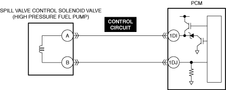
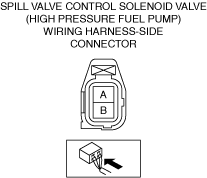
INSPECT SPILL VALVE CONTROL SOLENOID VALVE CONTROL CIRCUIT FOR SHORT TO GROUND
• Inspect the applicable circuit for a short to ground. (See CIRCUIT INSPECTION.)
• Is the circuit normal?
|
Yes
|
Replace the high pressure fuel pump and perform the repair completion verification.
|
|
No
|
Repair or replace the malfunctioning location and perform the repair completion verification.
|
||
|
13
|
INSPECT FUEL PRESSURE (LOW-SIDE)
• Connect the fuel pressure gauge between fuel pump and high pressure fuel pump.
• Measure the low side fuel pressure. (See FUEL LINE PRESSURE INSPECTION [SKYACTIV-G (WITH CYLINDER DEACTIVATION (US))].) (See FUEL LINE PRESSURE INSPECTION [SKYACTIV-G (WITHOUT CYLINDER DEACTIVATION (US))].)
• Is the low side fuel pressure within specification?
Specification:
• 475—555 kPa {4.85—5.65 kgf/cm2, 68.9—80.4 psi}
|
Yes
|
Go to the next step.
|
|
No
|
Inspect the following:
• Fuel line restriction
• Fuel filter clogged
|
||
|
14
|
INSPECT IGNITION SYSTEM OPERATION
• Perform the Spark Test. (See SPARK INSPECTION [SKYACTIV-G (WITH CYLINDER DEACTIVATION (US))].) (See SPARK INSPECTION [SKYACTIV-G (WITHOUT CYLINDER DEACTIVATION (US))].)
• Is a strong blue spark visible at each cylinder?
|
Yes
|
Go to the next step.
|
|
No
|
Repair or replace the malfunctioning location and perform the repair completion verification.
|
||
|
15
|
INSPECT ENGINE COMPRESSION
• Measure the compression pressure for each cylinder. (See COMPRESSION INSPECTION [SKYACTIV-G (WITH CYLINDER DEACTIVATION (US))].) (See COMPRESSION INSPECTION [SKYACTIV-G (WITHOUT CYLINDER DEACTIVATION (US))].)
• Are compression pressures within specification?
|
Yes
|
Injector driver malfunction.
• Replace the PCM. (See PCM REMOVAL/INSTALLATION [SKYACTIV-G (WITH CYLINDER DEACTIVATION (US))].) (See PCM REMOVAL/INSTALLATION [SKYACTIV-G (WITHOUT CYLINDER DEACTIVATION (US))].)
If the problem remains, overhaul the engine and perform the repair completion verification.
|
|
No
|
Inspect the following:
• Damaged valve seat
• Worn valve stem and valve guide
• Worn or stuck piston ring
• Worn piston, piston ring or cylinder
• Improper intake valve timing
• Improper exhaust valve timing
Repair or replace the malfunctioning location and perform the repair completion verification.
|
||
|
Repair completion verification 1
|
VERIFY THAT VEHICLE IS REPAIRED
• Install/connect the part removed/disconnected during the troubleshooting procedure.
• Has the malfunction symptom been eliminated?
|
Yes
|
Complete the symptom troubleshooting. (Explain contents of repair to customer)
|
|
No
|
Refer to the controller area network (CAN) malfunction diagnosis flow to inspect for a CAN communication error.
• If the CAN communication is normal, perform the diagnosis from Step 1.
|
||
|
Repair completion verification 2
|
VERIFY IF MALFUNCTION IS CAUSED BY NOT PERFORMING PCM REPROGRAMMING
• Verify repair information and verify that there is a new calibration in the PCM.
• Is there a new calibration in the PCM?
|
Yes
|
Perform the PCM reprogramming and verify if the malfunction symptom was corrected.
• If the malfunction recurs, replace the PCM. (See PCM REMOVAL/INSTALLATION [SKYACTIV-G (WITH CYLINDER DEACTIVATION (US))].) (See PCM REMOVAL/INSTALLATION [SKYACTIV-G (WITHOUT CYLINDER DEACTIVATION (US))].)
|
|
No
|
Replace the PCM.
|