DETERMINING SHORT TO POWER SUPPLY LOCATION (CAN-BUS No.1) [(US)]
DETERMINING SHORT TO POWER SUPPLY LOCATION (CAN-BUS No.1) [(US)]
SM2566445
id1002x1001900
-
Caution
-
• Perform the following malfunction diagnosis only when it is diagnosed with a short to ground by CONTROLLER AREA NETWORK (CAN) MALFUNCTION DIAGNOSIS FLOW. (See CONTROLLER AREA NETWORK (CAN) MALFUNCTION DIAGNOSIS FLOW [(US)].)
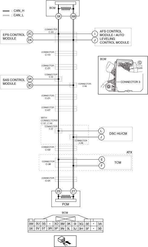
System Wiring Diagram
am3zzw00027512
|
Determination Procedure
-
Caution
-
• When disconnecting the connector, verify that there is no looseness, damage, deformation, corrosion, or poor connection of the connector terminals.• When inspecting the connector, touch it with a paper clip or similar thin pin without directly inserting a tester probe into the terminal.• Disconnect the negative battery terminal before performing any work that requires handling of connectors.
|
Step |
Inspection |
Action |
|
|---|---|---|---|
|
1
|
INSPECT CAN LINE BETWEEN BODY CONTROL MODULE (BCM) AND CONNECTOR C-40 FOR SHORT TO POWER SUPPLY
• Switch the ignition off.
• Disconnect the negative battery terminal. (See NEGATIVE BATTERY TERMINAL DISCONNECTION/CONNECTION [(US)].)
• Disconnect the connector C-40.
• Connect the negative battery terminal. (See NEGATIVE BATTERY TERMINAL DISCONNECTION/CONNECTION [(US)].)
• Switch the ignition ON (engine off).
• Measure the voltage at body control module (BCM) terminals 3X and 3W.
• Is the voltage between 1.5—3.5 V?
|
Yes
|
Go to Step 3.
|
|
No
|
Go to the next step.
|
||
|
2
|
INSPECT BODY CONTROL MODULE (BCM) FOR SHORT TO POWER SUPPLY
• Switch the ignition off.
• Disconnect the negative battery terminal. (See NEGATIVE BATTERY TERMINAL DISCONNECTION/CONNECTION [(US)].)
• Disconnect the connector 3 which has body control module (BCM) terminals 3X and 3W.
• Connect the connector C-40.
• Connect the negative battery terminal. (See NEGATIVE BATTERY TERMINAL DISCONNECTION/CONNECTION [(US)].)
• Switch the ignition ON (engine off).
• Measure the voltage at body control module (BCM) terminals 3X and 3W (wiring harness side).
• Is the voltage between 1.5—3.5 V?
|
Yes
|
Replace the body control module (BCM) because there is a short to the power supply in the body control module (BCM).
|
|
No
|
Repair or replace the wiring harness between the body control module (BCM) and connector C-40 because the wiring harness is shorted to the power supply.
|
||
|
3
|
INSPECT CAN LINE BETWEEN EPS CONTROL MODULE AND CONNECTOR C-40 FOR SHORT TO POWER SUPPLY
• Measure the voltage at EPS control module terminals 2C and 2A.
• Is the voltage between 1.5—3.5 V?
|
Yes
|
Go to Step 5.
|
|
No
|
Go to the next step.
|
||
|
4
|
INSPECT EPS CONTROL MODULE FOR SHORT TO POWER SUPPLY
• Switch the ignition off.
• Disconnect the negative battery terminal. (See NEGATIVE BATTERY TERMINAL DISCONNECTION/CONNECTION [(US)].)
• Disconnect the EPS control module connector.
• Connect the connector C-40.
• Connect the negative battery terminal. (See NEGATIVE BATTERY TERMINAL DISCONNECTION/CONNECTION [(US)].)
• Switch the ignition ON (engine off).
• Measure the voltage at body control module (BCM) terminals 3X and 3W.
• Is the voltage between 1.5—3.5 V?
|
Yes
|
Replace the EPS control module because there is a short to the power supply in the EPS control module.
|
|
No
|
Repair or replace the wiring harness between the EPS control module and connector C-40 because the wiring harness is shorted to the power supply.
|
||
|
5
|
INSPECT CAN LINE BETWEEN AFS CONTROL MODULE / AUTO LEVELING CONTROL MODULE AND CONNECTOR C-40 FOR SHORT TO POWER SUPPLY
• Measure the voltage at AFS control module / auto leveling control module terminals I and J.
• Is the voltage between 1.5—3.5 V?
|
Yes
|
Go to Step 7.
|
|
No
|
Go to the next step.
|
||
|
6
|
INSPECT AFS CONTROL MODULE / AUTO LEVELING CONTROL MODULE FOR SHORT TO POWER SUPPLY
• Switch the ignition off.
• Disconnect the negative battery terminal. (See NEGATIVE BATTERY TERMINAL DISCONNECTION/CONNECTION [(US)].)
• Disconnect the AFS control module / auto leveling control module connector.
• Connect the connector C-40.
• Connect the negative battery terminal. (See NEGATIVE BATTERY TERMINAL DISCONNECTION/CONNECTION [(US)].)
• Switch the ignition ON (engine off).
• Measure the voltage at body control module (BCM) terminals 3X and 3W.
• Is the voltage between 1.5—3.5 V?
|
Yes
|
Replace the AFS control module / auto leveling control module because there is a short to the power supply in the AFS control module / auto leveling control module.
|
|
No
|
Repair or replace the wiring harness between the AFS control module / auto leveling control module and connector C-40 because the wiring harness is shorted to the power supply.
|
||
|
7
|
INSPECT CAN LINE BETWEEN CONNECTOR C-13 AND CONNECTOR C-40 FOR SHORT TO POWER SUPPLY
• Switch the ignition off.
• Disconnect the negative battery terminal. (See NEGATIVE BATTERY TERMINAL DISCONNECTION/CONNECTION [(US)].)
• Disconnect the connector C-13.
• Connect the connector C-40.
• Connect the negative battery terminal. (See NEGATIVE BATTERY TERMINAL DISCONNECTION/CONNECTION [(US)].)
• Switch the ignition ON (engine off).
• Measure the voltage at body control module (BCM) terminals 3X and 3W.
• Is the voltage between 1.5—3.5 V?
|
Yes
|
Go to the next step.
|
|
No
|
Repair or replace the wiring harness between the connector C-13 and connector C-40 because the wiring harness is shorted to the power supply.
|
||
|
8
|
INSPECT CAN LINE BETWEEN CONNECTOR C-21 AND CONNECTOR C-13 FOR SHORT TO POWER SUPPLY
• Switch the ignition off.
• Disconnect the negative battery terminal. (See NEGATIVE BATTERY TERMINAL DISCONNECTION/CONNECTION [(US)].)
• Disconnect the connector C-21.
• Connect the connector C-13.
• Connect the negative battery terminal. (See NEGATIVE BATTERY TERMINAL DISCONNECTION/CONNECTION [(US)].)
• Switch the ignition ON (engine off).
• Measure the voltage at body control module (BCM) terminals 3X and 3W.
• Is the voltage between 1.5—3.5 V?
|
Yes
|
Go to the next step.
|
|
No
|
Repair or replace the wiring harness between the connector C-21 and connector C-13 because the wiring harness is shorted to the power supply.
|
||
|
9
|
INSPECT CAN LINE BETWEEN CONNECTOR C-21 AND PCM FOR SHORT TO POWER SUPPLY
• Measure the voltage at PCM terminals 2S and 2T.
• Is the voltage between 1.5—3.5 V?
|
Yes
|
Go to the next step.
|
|
No
|
Go to Step 13.
|
||
|
10
|
INSPECT CAN LINE BETWEEN CONNECTOR C-21 AND CONNECTORS C-55, C-56 FOR SHORT TO POWER SUPPLY
• Switch the ignition off.
• Disconnect the negative battery terminal. (See NEGATIVE BATTERY TERMINAL DISCONNECTION/CONNECTION [(US)].)
• Disconnect the connectors C-55, C-56.
• Connect the connector C-21.
• Connect the negative battery terminal. (See NEGATIVE BATTERY TERMINAL DISCONNECTION/CONNECTION [(US)].)
• Switch the ignition ON (engine off).
• Measure the voltage at body control module (BCM) terminals 3X and 3W.
• Is the voltage between 1.5—3.5 V?
|
Yes
|
Go to the next step.
|
|
No
|
Repair or replace the wiring harness between connector C-21 and connectors C-55, C-56 because the wiring harness is shorted to the power supply.
|
||
|
11
|
INSPECT CAN LINE BETWEEN SAS CONTROL MODULE AND CONNECTORS C-55, C-56 FOR SHORT TO POWER SUPPLY
• Measure the voltage at PCM terminals 2S and 2T.
• Is the voltage between 1.5—3.5 V?
|
Yes
|
Go to the next step.
|
|
No
|
Repair or replace the wiring harness between the connectors C-55, C-56 and connector C-21 because the wiring harness is shorted to the power supply.
|
||
|
12
|
INSPECT SAS CONTROL MODULE FOR SHORT TO POWER SUPPLY
• Switch the ignition off.
• Disconnect the negative battery terminal. (See NEGATIVE BATTERY TERMINAL DISCONNECTION/CONNECTION [(US)])
• Disconnect the SAS control module connector.
• Connect the negative battery terminal. (See NEGATIVE BATTERY TERMINAL DISCONNECTION/CONNECTION [(US)])
• Switch the ignition ON (engine off).
• Inspect for continuity between SAS control module terminals 3A and 3D (wiring harness side).
• Is the voltage 0 V?
|
Yes
|
Replace the SAS control module connector because there is a short to the power supply in the SAS control module connector.
|
|
No
|
Repair or replace the wiring harness between the SAS control module and connectors C-55, C-56 because the wiring harness is shorted to the power supply.
|
||
|
13
|
INSPECT CAN LINE BETWEEN CONNECTOR C-07 AND CONNECTOR C-21 FOR SHORT TO POWER SUPPLY
• Switch the ignition off.
• Disconnect the negative battery terminal. (See NEGATIVE BATTERY TERMINAL DISCONNECTION/CONNECTION [(US)].)
• Disconnect the connector C-07.
• Connect the connector C-21.
• Connect the negative battery terminal. (See NEGATIVE BATTERY TERMINAL DISCONNECTION/CONNECTION [(US)].)
• Switch the ignition ON (engine off).
• Measure the voltage at body control module (BCM) terminals 3X and 3W.
• Is the voltage between 1.5—3.5 V?
|
Yes
|
• Go to the next step. (with connectors C-37, C-36)
• Go to Step 18. (without connectors C-37, C-36)
|
|
No
|
Repair or replace the wiring harness between the connector C-07 and connector C-21 because the wiring harness is shorted to the power supply.
|
||
|
14
|
INSPECT CAN LINE BETWEEN CONNECTORS C-37, C-36 AND CONNECTOR C-07 FOR SHORT TO POWER SUPPLY
• Switch the ignition off.
• Disconnect the negative battery terminal. (See NEGATIVE BATTERY TERMINAL DISCONNECTION/CONNECTION [(US)].)
• Disconnect the connectors C-37, C-36.
• Connect the connector C-07.
• Connect the negative battery terminal. (See NEGATIVE BATTERY TERMINAL DISCONNECTION/CONNECTION [(US)].)
• Switch the ignition ON (engine off).
• Measure the voltage at body control module (BCM) terminals 3X and 3W.
• Is the voltage between 1.5—3.5 V?
|
Yes
|
Go to the next step.
|
|
No
|
Repair or replace the wiring harness between the connectors C-37, C-36 and connector C-07 because the wiring harness is shorted to the power supply.
|
||
|
15
|
INSPECT CAN LINE BETWEEN DSC HU/CM AND CONNECTORS C-37, C-36 FOR SHORT TO POWER SUPPLY
• Measure the voltage at DSC HU/CM terminals L and J.
• Is the voltage between 1.5—3.5 V?
|
Yes
|
Go to Step 17.
|
|
No
|
Go to the next step.
|
||
|
16
|
INSPECT DSC HU/CM FOR SHORT TO POWER SUPPLY
• Switch the ignition off.
• Disconnect the negative battery terminal. (See NEGATIVE BATTERY TERMINAL DISCONNECTION/CONNECTION [(US)].)
• Disconnect the DSC HU/CM connector.
• Connect the connectors C-37, C-36.
• Connect the negative battery terminal. (See NEGATIVE BATTERY TERMINAL DISCONNECTION/CONNECTION [(US)].)
• Switch the ignition ON (engine off).
• Measure the voltage at body control module (BCM) terminals 3X and 3W.
• Is the voltage between 1.5—3.5 V?
|
Yes
|
Replace the DSC HU/CM because there is a short to the power supply in the DSC HU/CM.
|
|
No
|
Repair or replace the wiring harness between the DSC HU/CM and connectors C-37, C-36 because the wiring harness is shorted to the power supply.
|
||
|
17
|
INSPECT CAN LINE BETWEEN CONNECTORS C-37, C-36 AND CONNECTOR C-02 FOR SHORT TO POWER SUPPLY
• Switch the ignition off.
• Disconnect the negative battery terminal. (See NEGATIVE BATTERY TERMINAL DISCONNECTION/CONNECTION [(US)].)
• Disconnect the connector C-02.
• Connect the connectors C-37, C-36.
• Connect the negative battery terminal. (See NEGATIVE BATTERY TERMINAL DISCONNECTION/CONNECTION [(US)].)
• Switch the ignition ON (engine off).
• Measure the voltage at body control module (BCM) terminals 3X and 3W.
• Is the voltage between 1.5—3.5 V?
|
Yes
|
Go to Step 20.
|
|
No
|
Repair or replace the wiring harness between the connectors C-37, C-36 and connector C-02 because the wiring harness is shorted to the power supply.
|
||
|
18
|
INSPECT CAN LINE BETWEEN CONNECTOR C-02 AND CONNECTOR C-07 FOR SHORT TO POWER SUPPLY
• Switch the ignition off.
• Disconnect the negative battery terminal. (See NEGATIVE BATTERY TERMINAL DISCONNECTION/CONNECTION [(US)].)
• Disconnect the connector C-02.
• Connect the connector C-07.
• Connect the negative battery terminal. (See NEGATIVE BATTERY TERMINAL DISCONNECTION/CONNECTION [(US)].)
• Switch the ignition ON (engine off).
• Measure the voltage at body control module (BCM) terminals 3X and 3W.
• Is the voltage between 1.5—3.5 V?
|
Yes
|
Go to Step 20.
|
|
No
|
Go to the next step.
|
||
|
19
|
INSPECT DSC HU/CM FOR SHORT TO POWER SUPPLY
• Switch the ignition off.
• Disconnect the negative battery terminal. (See NEGATIVE BATTERY TERMINAL DISCONNECTION/CONNECTION [(US)].)
• Disconnect the DSC HU/CM connector.
• Connect the negative battery terminal. (See NEGATIVE BATTERY TERMINAL DISCONNECTION/CONNECTION [(US)].)
• Switch the ignition ON (engine off).
• Measure the voltage at body control module (BCM) terminals 3X and 3W.
• Is the voltage between 1.5—3.5 V?
|
Yes
|
Replace the DSC HU/CM because there is a short to the power supply in the DSC HU/CM.
|
|
No
|
Repair or replace the wiring harness between connector C-07 and connector C-02 because the wiring harness is shorted to the power supply.
|
||
|
20
|
INSPECT CAN LINE BETWEEN CONNECTOR C-38 AND CONNECTOR C-02 FOR SHORT TO POWER SUPPLY
• Switch the ignition off.
• Disconnect the negative battery terminal. (See NEGATIVE BATTERY TERMINAL DISCONNECTION/CONNECTION [(US)].)
• Disconnect the connector C-38.
• Connect the connector C-02.
• Connect the negative battery terminal. (See NEGATIVE BATTERY TERMINAL DISCONNECTION/CONNECTION [(US)].)
• Switch the ignition ON (engine off).
• Measure the voltage at body control module (BCM) terminals 3X and 3W.
• Is the voltage between 1.5—3.5 V?
|
Yes
|
Go to the next step.
|
|
No
|
Repair or replace the wiring harness between connector C-38 and connector C-02 because the wiring harness is shorted to the power supply.
|
||
|
21
|
INSPECT CAN LINE BETWEEN TCM AND CONNECTOR C-38 FOR SHORT TO POWER SUPPLY
• Measure the voltage at TCM terminals E and F.
• Is the voltage between 1.5—3.5 V?
|
Yes
|
Go to Step 23.
|
|
No
|
Go to the next step.
|
||
|
22
|
INSPECT TCM FOR SHORT TO POWER SUPPLY
• Switch the ignition off.
• Disconnect the negative battery terminal. (See NEGATIVE BATTERY TERMINAL DISCONNECTION/CONNECTION [(US)].)
• Disconnect the TCM connector.
• Connect the connector C-38.
• Connect the negative battery terminal. (See NEGATIVE BATTERY TERMINAL DISCONNECTION/CONNECTION [(US)].)
• Switch the ignition ON (engine off).
• Measure the voltage at body control module (BCM) terminals 3X and 3W.
• Is the voltage between 1.5—3.5 V?
|
Yes
|
Replace the TCM because there is a short to the power supply in the TCM.
|
|
No
|
Repair or replace the wiring harness between the TCM and connector C-38 because the wiring harness is shorted to the power supply.
|
||
|
23
|
INSPECT CAN LINE BETWEEN CONNECTOR C-38 AND CONNECTOR C-01 FOR SHORT TO POWER SUPPLY
• Switch the ignition off.
• Disconnect the negative battery terminal. (See NEGATIVE BATTERY TERMINAL DISCONNECTION/CONNECTION [(US)].)
• Disconnect the connector C-01.
• Connect the connector C-38.
• Connect the negative battery terminal. (See NEGATIVE BATTERY TERMINAL DISCONNECTION/CONNECTION [(US)].)
• Switch the ignition ON (engine off).
• Measure the voltage at body control module (BCM) terminals 3X and 3W.
• Is the voltage between 1.5—3.5 V?
|
Yes
|
Go to the next step.
|
|
No
|
Repair or replace the wiring harness between connector C-38 and connector C-01 because the wiring harness is shorted to the power supply.
|
||
|
24
|
INSPECT PCM FOR SHORT TO POWER SUPPLY
• Switch the ignition off.
• Disconnect the negative battery terminal. (See NEGATIVE BATTERY TERMINAL DISCONNECTION/CONNECTION [(US)].)
• Disconnect the PCM connector.
• Connect the connector C-38.
• Connect the negative battery terminal. (See NEGATIVE BATTERY TERMINAL DISCONNECTION/CONNECTION [(US)].)
• Switch the ignition ON (engine off).
• Measure the voltage at body control module (BCM) terminals 3X and 3W.
• Is the voltage between 1.5—3.5 V?
|
Yes
|
Replace the PCM because there is a short to the power supply in the PCM.
|
|
No
|
Repair or replace the wiring harness between the PCM and connector C-38 because the wiring harness is shorted to the power supply.
|
||