SAS CONTROL MODULE REMOVAL/INSTALLATION [TWO-STEP DEPLOYMENT CONTROL SYSTEM – US/CANADA SPEC.]
SAS CONTROL MODULE REMOVAL/INSTALLATION [TWO-STEP DEPLOYMENT CONTROL SYSTEM – US/CANADA SPEC.]
SM2335910
id0810b4801400
-
Warning
-
• Handling the SAS control module improperly can accidentally operate (deploy) the air bag module and pre-tensioner seat belt, which may seriously injure you. Read the air bag system service warnings and cautions before handling the SAS control module. (See AIR BAG SYSTEM SERVICE WARNINGS [TWO-STEP DEPLOYMENT CONTROL SYSTEM – US/CANADA SPEC.].) (See AIR BAG SYSTEM SERVICE CAUTIONS [TWO-STEP DEPLOYMENT CONTROL SYSTEM – US/CANADA SPEC.].)• If the connector is connected and the ignition switch is turned to the ON position with the SAS control module not secured completely using the installation nuts, the SAS control module may detect a degree of impact even when something contacts it lightly, deploying the air bag module and pre-tensioner seat belt accidentally.
-
Caution
-
• When replacing the SAS control module, perform the configuration to assure that the system operates correctly. (See CONFIGURATION.)
1.When replacing the SAS control module, perform manual configuration using the following procedure.
- (1)Verify the personalization feature setting values with the customer.
- (2)Connect the M-MDS to the DLC-2.
- (3)Switch the ignition ON (engine off or on).
- (4)Perform vehicle identification.
- (5)Select [Configuration] using the M-MDS.
- (6)Select [SAS].
- (7)Perform manual configuration following the instructions on the screen.
2.Switch the ignition off.
3.Disconnect the negative battery terminal and wait for 1 min or more. (See NEGATIVE BATTERY TERMINAL DISCONNECTION/CONNECTION [(US)].)
4.Remove the following parts:
- (1)Selector lever knob (ATX) (See SELECTOR LEVER COMPONENT REMOVAL/INSTALLATION.)
- (2)Shift lever knob (MTX) (See SHIFT LEVER REMOVAL/INSTALLATION [C66M-R].)
- (3)Shift panel (See SHIFT PANEL REMOVAL/INSTALLATION.)
- (4)Front console box (See FRONT CONSOLE BOX REMOVAL/INSTALLATION.)
- (5)Cup holder (See CUP HOLDER REMOVAL/INSTALLATION.)
- (6)Side wall (See SIDE WALL REMOVAL/INSTALLATION.)
- (7)Rear console (See REAR CONSOLE REMOVAL/INSTALLATION [(US)].)
5.Pull out the SAS control module connectors lock lever in the direction of arrow shown in the figure.
am3zzw00031996
|
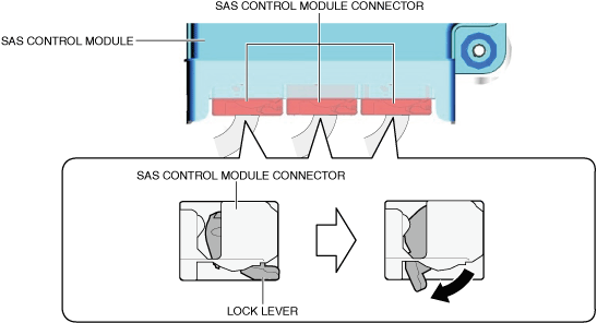
6.Disconnect the SAS control module connectors.
am3zzw00024415
|
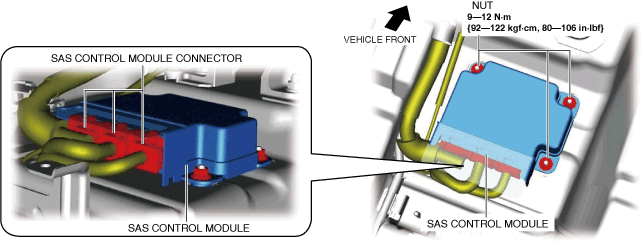
7.Remove the nuts.
8.Remove the SAS control module.
9.Install in the reverse order of removal.
10.If the SAS control module is replaced, perform the following procedure.
- (1)Perform manual configuration following the instructions on the M-MDS screen.
-
-
• If manual configuration is performed using the As-Built data, the set values for the personalization features may be reset to the initial values (condition when shipped from factory). Perform the personalization features setting after performing the manual configuration.
-
- (2)Perform the following initial setting using the M-MDS. (See DSC RELATED PARTS SENSOR INITIALIZATION PROCEDURE [(US)].) (See VCM INITIAL SETTING.)
-
-
• Calibrating Lateral G Sensor for DSC
-
• Calibrating Longitudinal G Sensor for DSC
-
• Calibrating Yaw Rate for DSC
-
• Calibrating Yaw Rate for VCM
-
- (3)Clear the DTC. (See CLEARING DTC.)
- (4)Switch the ignition ON (engine off or on).
- (5)Verify that the air bag/front seat belt pre-tensioner system warning light turns on for approx. 6 s and turns off.
-
-
• If the air bag/front seat belt pre-tensioner system warning light does not operate properly, refer to the on-board diagnostic system and inspect the system. (See DTC INSPECTION.)
-