AUTOMATIC TRANSAXLE REMOVAL/INSTALLATION [EV6A-EL]
AUTOMATIC TRANSAXLE REMOVAL/INSTALLATION [EV6A-EL]
SM2566190
id0517o31172n2
Special Service Tool (SST)
|
1. : Mazda SST number
2. : Global SST number
|
|||||
|
1: 49 C017 5A0
2: –
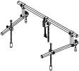
Engine support set
|
 |
1: 49 UN30 3050
2: 303–050
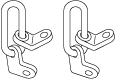
Engine lifting bracket
|
 |
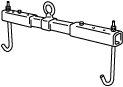
1: 49 L017 5A0
2: –
Support hanger
|
 |
-
Caution
-
• If the automatic transaxle has been replaced, perform TCM configuration. (See TCM CONFIGURATION [EV6A-EL, EV6AX-EL].)• If the automatic transaxle has been replaced, perform initial learning. (See INITIAL LEARNING [EV6A-EL, EV6AX-EL].)• Performing the following procedures could cause an open circuit in the front ABS wheel-speed sensor wiring harness if it is pulled by mistake. Before servicing, disconnect the front ABS wheel-speed sensor and set it aside so that the wiring harness will not be pulled by mistake.• Secure the steering wheel using tape or a cable to prevent the steering shaft from rotating after disconnecting the steering shaft. If the steering wheel rotates after the steering shaft and the steering gear and linkage are disconnected, the internal parts of the clock spring could be damaged.
Removal
1.Disconnect the negative battery terminal. (See NEGATIVE BATTERY TERMINAL DISCONNECTION/CONNECTION [(US)].)
2.Remove the plug hole plate. (See PLUG HOLE PLATE REMOVAL/INSTALLATION [SKYACTIV-G (WITH CYLINDER DEACTIVATION (US))].)
3.Remove the following parts as a single unit. (See INTAKE-AIR SYSTEM REMOVAL/INSTALLATION [SKYACTIV-G (WITH CYLINDER DEACTIVATION (US))].)
-
• Air cleaner cover• Air cleaner element• Fresh-air duct• Air cleaner case• Air hose• Resonance chamber
4.Remove the battery. (See BATTERY REMOVAL/INSTALLATION [SKYACTIV-G (WITH CYLINDER DEACTIVATION (US))].)
5.Remove the battery tray and PCM component as a single unit. (See BATTERY REMOVAL/INSTALLATION [SKYACTIV-G (WITH CYLINDER DEACTIVATION (US))].)
6.Remove the front deflector. (See DEFLECTOR REMOVAL/INSTALLATION.)
7.Remove the front splash shield. (See SPLASH SHIELD REMOVAL/INSTALLATION.)
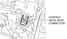
8.Disconnect the control valve body connector.
-
Caution
-
• Make sure that your hand does not touch the terminal as the connector terminal could be damaged.• Water or foreign matter entering the connector can cause a poor connection or corrosion. Be careful not to allow water droplets or foreign matter to get on the connector when disconnecting it.
 am3zzw00022344
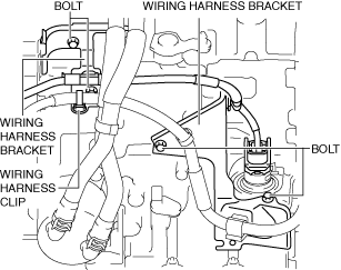
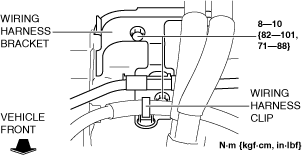
9.Remove the wiring harness clip and bolts, and set the wiring harnesses and wiring harness brackets in a place which does not interfere with servicing.
am3zzw00022744
|
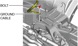
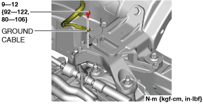
10.Disconnect the ground cable.
am3zzw00021743
|
11.Disconnect the selector cable from the transaxle. (See SELECTOR CABLE REMOVAL/INSTALLATION [(US)].)
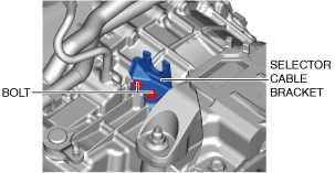
12.Remove the selector cable bracket.
am3zzw00021744
|
13.Remove the bracket.
am3zzw00031537
|
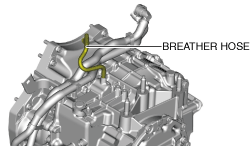
14.Disconnect the breather hose from the transaxle.
am3zzw00021745
|
15.Remove the joint cover. (See STEERING WHEEL AND COLUMN REMOVAL/INSTALLATION [(US)].)
16.Disconnect the intermediate shaft from the steering gear and linkage. (See STEERING WHEEL AND COLUMN REMOVAL/INSTALLATION [(US)].)
17.Remove the front tires. (See WHEEL AND TIRE REMOVAL/INSTALLATION.)
18.Remove the tunnel cover. (See EXHAUST SYSTEM REMOVAL/INSTALLATION [SKYACTIV-G (WITH CYLINDER DEACTIVATION (US))].)
19.Remove the front under cover No.2. (See FRONT UNDER COVER No.2 REMOVAL/INSTALLATION.)
20.Remove the front under cover No.1. (See FRONT UNDER COVER No.1 REMOVAL/INSTALLATION.)
21.Drain the engine coolant. (See ENGINE COOLANT REPLACEMENT [SKYACTIV-G (WITH CYLINDER DEACTIVATION (US))].)
22.Drain the ATF. (See AUTOMATIC TRANSAXLE FLUID (ATF) REPLACEMENT [EV6A-EL, EV6AX-EL].)
23.Remove the oil cooler and water hose component as a single unit. (Except automatic transaxle replacement) (See OIL COOLER REMOVAL/INSTALLATION [EV6A-EL, EV6AX-EL].)
24.Remove the water hose component. (Automatic transaxle replacement) (See OIL COOLER REMOVAL/INSTALLATION [EV6A-EL, EV6AX-EL].)
25.Remove the lower radiator hose component. (See RADIATOR REMOVAL/INSTALLATION [SKYACTIV-G (WITH CYLINDER DEACTIVATION (US))].) (See COOLANT CONTROL VALVE REMOVAL/INSTALLATION [SKYACTIV-G (WITH CYLINDER DEACTIVATION (US))].)
26.Remove the starter. (See STARTER REMOVAL/INSTALLATION [SKYACTIV-G (WITH CYLINDER DEACTIVATION (US))].)
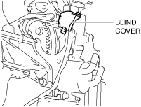
27.Remove the blind cover.
am3zzw00022347
|
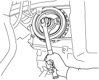
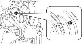
28.Hold the crankshaft pulley to prevent drive plate from rotating.
am3uuw00002582
|
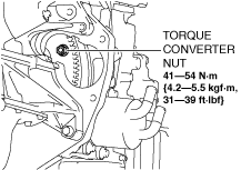
29.Remove the torque converter nuts from the starter installation hole.
am3zzw00031538
|
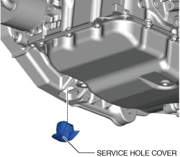
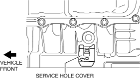
30.Remove the service hole cover.
am3zzw00021746
|
31.Disconnect the tie-rod ends from the steering knuckles. (See TIE-ROD END REPLACEMENT.)
32.Disconnect the front lower arm ball joints from the steering knuckle. (See FRONT LOWER ARM REMOVAL/INSTALLATION [(US)].)
33.Disconnect the front drive shaft (LH) from the transaxle. (See FRONT DRIVE SHAFT REMOVAL/INSTALLATION [(US)].)
34.Disconnect the front drive shaft (RH) from the transaxle. (See FRONT DRIVE SHAFT REMOVAL/INSTALLATION [(US)].)
35.Remove the front crossmember component and No.1 engine mount rubber as a single unit. (See FRONT CROSSMEMBER REMOVAL/INSTALLATION [(US)].)
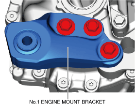
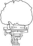
36.Remove the No.1 engine mount bracket from the transaxle.
am3zzw00021747
|
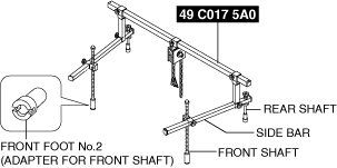
37.Install the SST using the following procedures.
ac5uuw00006422
|
-
Caution
-
• Refer to the SST instruction manual for the basic handing procedure.
- (1)Install one front foot No.2 to each of the left and right front shafts of the SST.
- (2)Protect the positions shown in the area using tape.
-
am3zzw00022349
- (3)Remove the coolant reserve tank. (See COOLANT RESERVE TANK REMOVAL/INSTALLATION [SKYACTIV-G (WITH CYLINDER DEACTIVATION (US))].)
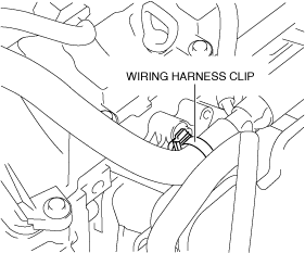
- (4)To enable installation of the SST, disconnect the wiring harness clip shown in the figure and set the wiring harness aside.
-
am3zzw00022745
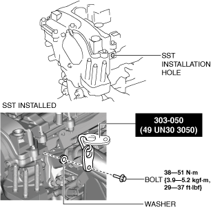
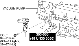
- (5)Install the SST using a bolt with part number 99794 1025 or an M10—1.25, length 25 mm {0.98 in} bolt, and a washer as shown in the figure.
-
Engine front side
am3zzw00032853Engine rear side
am3zzw00031540
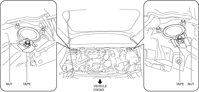
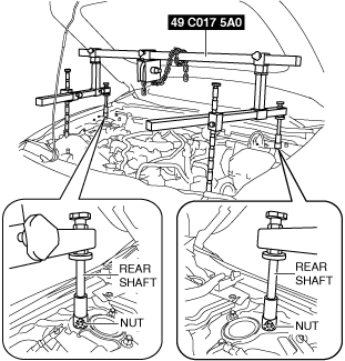
- (6)As shown in the figure, set the rear shafts of the SST to the left and right front shock absorber nuts.
-
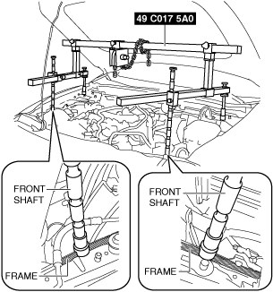
am3zzw00022352
- (7)Set the front shafts of the SST (49 C017 5A0) as shown in the figure.
-
am3zzw00022353
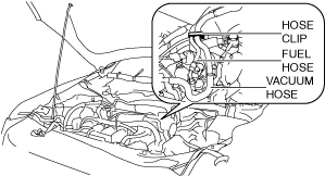
- (8)To prevent interference of the SST with the hose when assembling the SST (49 L017 5A0), disconnect the hose clip from the bracket shown in the figure and set the fuel hose and vacuum hose aside.
-
am3zzw00022354
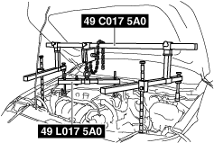
- (9)Install the SST (49 L017 5A0) to the SST (49 C017 5A0) as shown in the figure.
-
am3zzw00022355
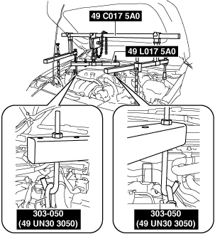
- (10)Install the SST (49 L017 5A0) to the SST (49 UN30 3050) with the hook of the SST (49 L017 5A0) facing outward.
-
am3zzw00022356
- (11)Adjust the height of the left and right side bars so that they are leveled, then tighten each part of the SST.
- (12)Apply tension to the chain to support the engine and verify that the engine is securely hung.
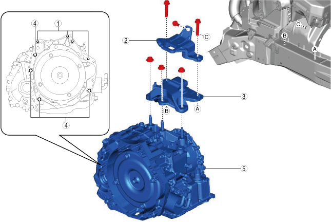
38.Remove in the order shown in the figure.
-
Warning
-
• Improperly jacking a transaxle is dangerous. It can slip off the jack and may cause serious injury.
-
Caution
-
• To prevent the torque converter and transaxle from separating, remove the transaxle without tilting it toward the torque converter.
am3zzw00021748
|
|
1
|
Transaxle mounting bolts (upper side)
|
|
2
|
No.4 engine mount bracket
|
|
3
|
No.4 engine mount rubber
|
|
4
|
Transaxle mounting bolts (lower side)
|
|
5
|
Transaxle
|
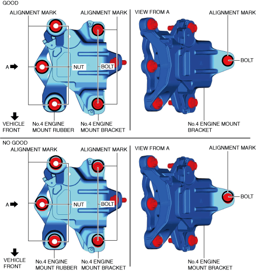
No.4 engine mount rubber and No.4 engine mount bracket removal note
-
Caution
-
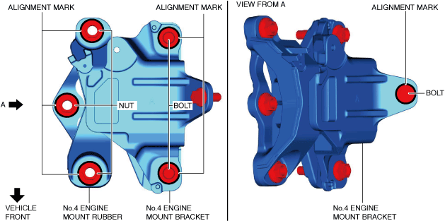
• Slots have been adopted for the No.4 engine mount rubber and No.4 engine mount bracket installation holes. If the No.4 engine mount rubber and No.4 engine mount bracket deviate from their original positions when they are installed, engine noise or vibration could increase. When installing the No.4 engine mount rubber and No.4 engine mount bracket, align them to the alignment marks placed during removal and install them to their original positions.
1.Place alignment marks on the locations shown in the figure so that they can be assembled to the same positions as before removal.
am3zzw00021749
|
-
Note
-
• Place the alignment marks so that the contour of the nuts and bolts are outlined.
2.Remove the No.4 engine mount rubber and the No.4 engine mount bracket.
Transaxle mounting bolt removal note
-
Warning
-
• Remove the transaxle carefully, holding it steady. If the transaxle falls it could be damaged or cause injury.
1.Adjust the SST and lean the engine toward the transaxle.
am3zzw00022355
|
2.Support the transaxle on a jack.
am3uuw00002584
|
3.Remove the transaxle mounting bolts (lower side).
4.Remove the transaxle.
Installation
-
Caution
-
• Verify that the torque converter stud bolts are inserted into the drive plate bolt holes, and install the transaxle installation bolts. Otherwise, the drive plate could be damaged.
1.Verify that the torque converter stud bolts are inserted into the drive plate bolt holes from the starter installation hole.
am3zzw00022357
|
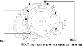
2.Install the transaxle mounting bolts.
am3zzw00031541
|
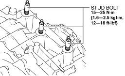
3.Tighten the stud bolts for the transaxle.
am3zzw00031542
|
-
Note
-
• If the No.4 engine mount bracket nut is loosened, tighten the stud bolts for the transaxle because they may be loosened.
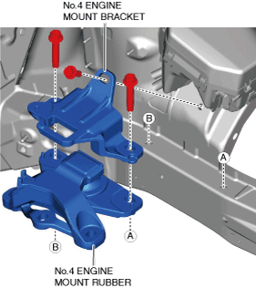
4.Install the No.4 engine mount bracket and the No.4 engine mount rubber, and temporarily tighten the bolts shown in the figure.
am3zzw00021751
|
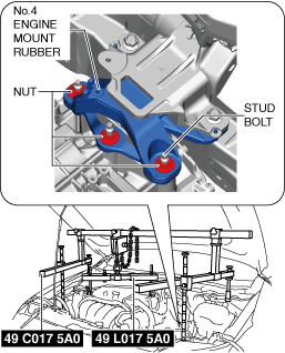
5.Lift up the transaxle using the SSTs, pass the stud bolt through the No.4 engine mount rubber, and temporarily tighten the No.4 engine mount rubber installation nuts.
am3zzw00022746
|
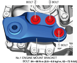
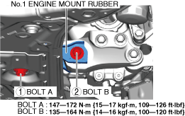
6.Install the No.1 engine mount bracket, and tighten the installation bolts in the order shown in the figure.
am3zzw00031543
|
7.Install the front crossmember component and No.1 engine mount rubber as a single unit. (See FRONT CROSSMEMBER REMOVAL/INSTALLATION [(US)].)
8.Temporarily tighten the No.1 engine mount rubber installation bolts.
am3zzw00021754
|
9.Align the nuts and bolts shown in the figure with the alignment marks.
am3zzw00021755
|
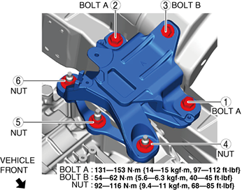
10.Tighten the No.4 engine mount rubber installation nuts and the No.4 engine mount bracket installation bolts in the order shown in the figure.
am3zzw00031544
|
11.Remove the SST (49 C017 5A0).
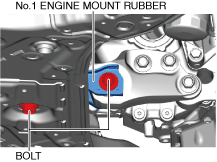
12.Tighten the No.1 engine mount rubber installation bolts in the order shown in the figure.
am3zzw00031545
|
13.Connect the hose clip to the bracket shown in the figure.
am3zzw00022354
|
14.Connect the wiring harness clip shown in the figure.
am3zzw00022745
|
15.Install the coolant reserve tank. (See COOLANT RESERVE TANK REMOVAL/INSTALLATION [SKYACTIV-G (WITH CYLINDER DEACTIVATION (US))].)
16.Fix the crankshaft pulley to lock the torque converter against rotation.
am3uuw00002582
|
-
Caution
-
• After temporarily tightening the torque converter installation nut uniformly, tighten it to the specified torque.
17.Tighten the torque converter installation nuts.
am3zzw00031538
|
18.Install the service hole cover using the following procedure.
- (1)Align the service hole cover so that its arrow is facing the front of the vehicle as shown in the figure.
-
am3zzw00031546
- (2)Move the service hole cover in the direction of arrow (1) shown in the figure and hook the service hole cover tab onto the converter housing.
-
am3zzw00031547
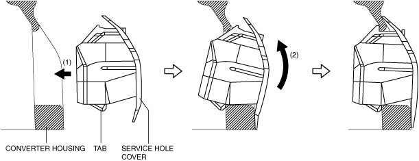
- (3)Install the service hole cover by pushing it in the direction of arrow (2) shown in the figure using the service hole cover tab as a pivot.
- (4)Verify that the service hole cover is securely installed.
19.Install the blind cover.
am3zzw00022347
|
20.Install the starter. (See STARTER REMOVAL/INSTALLATION [SKYACTIV-G (WITH CYLINDER DEACTIVATION (US))].)
21.Connect the front drive shaft (RH) to the transaxle. (See FRONT DRIVE SHAFT REMOVAL/INSTALLATION [(US)].)
22.Connect the front drive shaft (LH) to the transaxle. (See FRONT DRIVE SHAFT REMOVAL/INSTALLATION [(US)].)
23.Connect the front lower arm ball joint to the steering knuckles. (See FRONT LOWER ARM REMOVAL/INSTALLATION [(US)].)
24.Connect the tie-rod ends to the steering knuckles. (See TIE-ROD END REPLACEMENT.)
25.Install the lower radiator hose component. (See RADIATOR REMOVAL/INSTALLATION [SKYACTIV-G (WITH CYLINDER DEACTIVATION (US))].) (See COOLANT CONTROL VALVE REMOVAL/INSTALLATION [SKYACTIV-G (WITH CYLINDER DEACTIVATION (US))].)
26.Install the water hose component. (Automatic transaxle replacement) (See OIL COOLER REMOVAL/INSTALLATION [EV6A-EL, EV6AX-EL].)
27.Install the oil cooler and water hose component as a single unit. (Except automatic transaxle replacement) (See OIL COOLER REMOVAL/INSTALLATION [EV6A-EL, EV6AX-EL].)
28.Install the tunnel cover. (See EXHAUST SYSTEM REMOVAL/INSTALLATION [SKYACTIV-G (WITH CYLINDER DEACTIVATION (US))].)
29.Install the front tires. (See WHEEL AND TIRE REMOVAL/INSTALLATION.)
30.Connect the intermediate shaft to the steering gear and linkage. (See STEERING WHEEL AND COLUMN REMOVAL/INSTALLATION [(US)].)
31.Install the joint cover. (See STEERING WHEEL AND COLUMN REMOVAL/INSTALLATION [(US)].)
32.Connect the breather hose to the transaxle.
am3zzw00021745
|
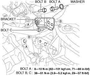
33.Install the bracket to the transaxle and the exhaust manifold using the following procedure:
am3zzw00031537
|
- (1)Tighten the bolt A.
- (2)Temporarily tighten the bolt B and C.
- (3)Tighten the bolt B.
- (4)Tighten the bolt C.
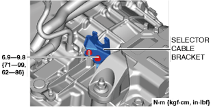
34.Install the selector cable bracket.
am3zzw00022851
|
35.Connect the selector cable to the transaxle. (See SELECTOR CABLE REMOVAL/INSTALLATION [(US)].)
36.Connect the ground cable to the No.4 engine mount rubber.
am3zzw00022852
|
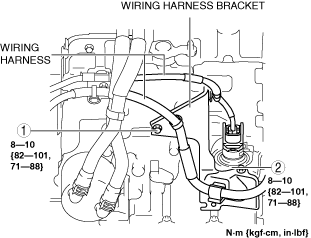
37.Install the wiring harness clip and wiring harness bracket.
am3zzw00022360
|
38.Tighten the wiring harness bracket installation bolts in the order shown in the figure.
am3zzw00031548
|
39.Connect the control valve body connector.
am3zzw00022344
|
-
Caution
-
• Make sure that your hand does not touch the terminal as the connector terminal could be damaged.• Verify that there is no fluid or foreign matter adhering to the connector before connecting the connector.• Insert the connector straight as the connector terminal could be damaged.• Rotate the connector lever until a click is heard.
40.Install the front splash shield. (See SPLASH SHIELD REMOVAL/INSTALLATION.)
41.Install the front deflector. (See DEFLECTOR REMOVAL/INSTALLATION.)
42.Install the battery tray and PCM component as a single unit. (See BATTERY REMOVAL/INSTALLATION [SKYACTIV-G (WITH CYLINDER DEACTIVATION (US))].)
43.Install the battery. (See BATTERY REMOVAL/INSTALLATION [SKYACTIV-G (WITH CYLINDER DEACTIVATION (US))].)
44.Install the following parts as a single unit. (See INTAKE-AIR SYSTEM REMOVAL/INSTALLATION [SKYACTIV-G (WITH CYLINDER DEACTIVATION (US))].)
-
• Air cleaner cover• Air cleaner element• Fresh-air duct• Air cleaner case• Air hose• Resonance chamber
45.Install the plug hole plate. (See PLUG HOLE PLATE REMOVAL/INSTALLATION [SKYACTIV-G (WITH CYLINDER DEACTIVATION (US))].)
46.Connect the negative battery terminal. (See NEGATIVE BATTERY TERMINAL DISCONNECTION/CONNECTION [(US)].)
47.Refill the engine coolant. (See ENGINE COOLANT REPLACEMENT [SKYACTIV-G (WITH CYLINDER DEACTIVATION (US))].)
48.Add the ATF. (See AUTOMATIC TRANSAXLE FLUID (ATF) REPLACEMENT [EV6A-EL, EV6AX-EL].)
49.Install the front under cover No.1. (See FRONT UNDER COVER No.1 REMOVAL/INSTALLATION.)
50.Install the front under cover No.2. (See FRONT UNDER COVER No.2 REMOVAL/INSTALLATION.)
51.Perform the “TCM configuration” (Automatic transaxle replacement). (See TCM CONFIGURATION [EV6A-EL, EV6AX-EL].)
52.Perform the “Initial Learning” (Automatic transaxle replacement). (See INITIAL LEARNING [EV6A-EL, EV6AX-EL].)
53.Perform the “Mechanical System Test”. (See MECHANICAL SYSTEM TEST [EV6A-EL, EV6AX-EL].)