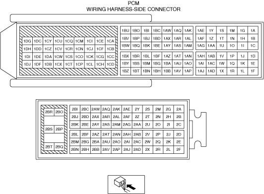
PCM INSPECTION [SKYACTIV-G (WITHOUT CYLINDER DEACTIVATION (US))]
PCM INSPECTION [SKYACTIV-G (WITHOUT CYLINDER DEACTIVATION (US))]
SM2565866
id0140u0802500
-
Note
-
• Because the PCM uses a waterproof connector, the inspection for the voltage/wave pattern cannot be performed. The following values are for reference.
Terminal voltage table (Reference)
am3zzw00034777
|
—: Not applicable
|
Terminal |
Signal |
Connected to |
Test condition |
Voltage (V) |
inspection item |
|
|---|---|---|---|---|---|---|
|
1A *1
|
CAN_2H
|
CAN system related modules
|
Because this terminal is for CAN, integrity determination by terminal voltage is not possible.
|
• Related wiring harness
|
||
|
1B *1
|
CAN_2L
|
CAN system related modules
|
Because this terminal is for CAN, integrity determination by terminal voltage is not possible.
|
• Related wiring harness
|
||
|
1C *2
|
Constant voltage (Vref)
|
Neutral sensor
|
Ignition switched ON (engine off)
|
Approx. 5.0
|
• Related wiring harness
|
|
|
1D
|
Constant voltage (Vref)
|
Engine oil pressure sensor, engine oil temperature sensor, coolant control valve position sensor, refrigerant pressure sensor No.2
|
Ignition switched ON (engine off)
|
Approx. 5.0
|
• Related wiring harness
|
|
|
1E
|
Constant voltage (Vref)
|
CKP sensor, revolution sensor
|
Ignition switched ON (engine off)
|
Approx. 5.0
|
• Related wiring harness
|
|
|
1F
|
CKP
|
CKP sensor
|
(See CKP signal.)
|
• CKP sensor
• Related wiring harness
|
||
|
1G
|
—
|
—
|
—
|
—
|
—
|
|
|
1H* 2
|
Neutral position
|
Neutral sensor
|
Shift lever is at neutral position
|
Below 1.0
|
• Neutral sensor
• Related wiring harness
|
|
|
Shift lever is not at neutral position
|
Approx. 4.5
|
|||||
|
1I
|
Coolant control valve position
|
Coolant control valve position sensor
|
Because this terminal is for SENT signal, integrity determination by terminal voltage is not possible.
|
• Coolant control valve position sensor
• Related wiring harness
|
||
|
1J
|
Constant voltage (Vref)
|
MAP sensor
|
Ignition switched ON (engine off)
|
Approx. 5.0
|
• Related wiring harness
|
|
|
1K
|
Constant voltage (Vref)
|
Fuel pressure sensor
|
Ignition switched ON (engine off)
|
Approx. 5.0
|
• Related wiring harness
|
|
|
1L
|
Constant voltage (Vref)
|
TP sensor No.1, TP sensor No.2
|
Ignition switched ON (engine off)
|
Approx. 5.0
|
• Related wiring harness
|
|
|
1M
|
A/F
|
A/F sensor
|
Ignition switched ON (engine off)
|
Approx. 5.0
|
• A/F sensor
• Related wiring harness
|
|
|
Idle (after warm up)
|
Approx. 4.1
|
|||||
|
1N
|
GND
|
Sensor shield
|
Under any condition
|
Below 1.0
|
• Related wiring harness
|
|
|
1O
|
TP (No.1)
|
TP sensor No.1
|
Ignition switched ON (engine off)
|
Accelerator pedal released
|
Approx. 1.11
|
• TP sensor No.1
• Related wiring harness
|
|
Accelerator pedal depressed
|
Approx. 4.59
|
|||||
|
1P
|
—
|
—
|
—
|
—
|
—
|
|
|
1Q
|
IAT (No.2)
|
IAT sensor No.2
|
Ignition switched ON (engine off)
|
IAT 20 °C
{68 °F}
|
Approx. 3.57
|
• IAT sensor No.2
• Related wiring harness
|
|
IAT 40 °C
{104 °F}
|
Approx. 2.70
|
|||||
|
IAT 60 °C
{140 °F}
|
Approx. 1.87
|
|||||
|
1R
|
GND
|
TP sensor No.1, TP sensor No.2
|
Under any condition
|
Below 1.0
|
• Related wiring harness
|
|
|
1S
|
A/F
|
A/F sensor
|
Idle (after warm up): 0 mA
|
• A/F sensor
• Related wiring harness
|
||
|
1T
|
A/F
|
A/F sensor
|
Idle (after warm up)
|
Approx. 4.1
|
• A/F sensor
• Related wiring harness
|
|
|
1U
|
GND
|
Sensor shield
|
Under any condition
|
Below 1.0
|
• Related wiring harness
|
|
|
1V
|
TP (No.2)
|
TP sensor No.2
|
Ignition switched ON (engine off)
|
Accelerator pedal released
|
Approx. 3.92
|
• TP sensor No.2
• Related wiring harness
|
|
Accelerator pedal depressed
|
Below 1.0
|
|||||
|
1W
|
Fuel pressure
|
Fuel pressure sensor
|
Ignition switched ON (engine off)
|
Approx. 0.57
|
• Fuel pressure sensor
• Related wiring harness
|
|
|
Idle (after warm up)
|
Approx. 1.51
|
|||||
|
1X
|
MAP
|
MAP sensor
|
Ignition switched ON (engine off)
|
Approx. 4.07
|
• MAP sensor
• Related wiring harness
|
|
|
Idle (after warm up)
|
Approx. 1.37
|
|||||
|
Racing
(Engine speed: 2,000 rpm)
|
Approx. 0.92
|
|||||
|
1Y
|
Knocking (+)
|
KS
|
Ignition switched ON (engine off) (Use digital type voltmeter, because measurement voltage will be detected less than true voltage when using analog type voltmeter)
|
Approx. 2.45
|
• KS
• Related wiring harness
|
|
|
1Z
|
Knocking (–)
|
KS
|
Ignition switched ON (engine off) (Use digital type voltmeter, because measurement voltage will be detected less than true voltage when using analog type voltmeter)
|
Below 1.0
|
• KS
• Related wiring harness
|
|
|
1AA
|
—
|
—
|
—
|
—
|
—
|
|
|
1AB
|
GND
|
Neutral sensor *2, ECT sensor No.1, ECT sensor No.2, engine oil pressure sensor, engine oil temperature sensor, engine oil level sensor
|
Under any condition
|
Below 1.0
|
• Related wiring harness
|
|
|
1AC *2
|
Revolution
|
Revolution sensor
|
(See Revolution sensor signal.)
|
• Revolution sensor
• Related wiring harness
|
||
|
1AD
|
Electric variable valve timing driver (diagnostic)
|
Electric variable valve timing driver
|
• Electric variable valve timing driver
• Related wiring harness
|
|||
|
1AE
|
Ion (No.2)
|
Ion sensor No.2
|
Idle (after warm up)
|
Approx. 4.4
|
• Ion sensor No.2
• Related wiring harness
|
|
|
1AF
|
Ion (No.4)
|
Ion sensor No.4
|
Idle (after warm up)
|
Approx. 4.4
|
• Ion sensor No.4
• Related wiring harness
|
|
|
1AG
|
Generator output voltage
|
Generator
|
(See Generator output voltage.)
|
• Generator
• Related wiring harness
|
||
|
1AH
|
ECT
|
ECT sensor No.1
|
Ignition switched ON (engine off)
|
ECT 20 °C
{68 °F}
|
Approx. 3.10
|
• ECT sensor No.1
• Related wiring harness
|
|
ECT 40 °C
{104 °F}
|
Approx. 2.16
|
|||||
|
ECT 60 °C
{140 °F}
|
Approx. 1.40
|
|||||
|
ECT 80 °C
{176 °F}
|
Approx. 0.87
|
|||||
|
ECT 100 °C
{212 °F}
|
Approx. 0.54
|
|||||
|
1AI
|
GND
|
Intake CMP sensor, exhaust CMP sensor
|
Under any condition
|
Below 1.0
|
• Related wiring harness
|
|
|
1AJ
|
—
|
—
|
—
|
—
|
—
|
|
|
1AK
|
Ion (No.3)
|
Ion sensor No.3
|
Idle (after warm up)
|
Approx. 4.4
|
• Ion sensor No.3
• Related wiring harness
|
|
|
1AL
|
Ion (No.1)
|
Ion sensor No.1
|
Idle (after warm up)
|
Approx. 4.4
|
• Ion sensor No.1
• Related wiring harness
|
|
|
1AM
|
ECT
|
ECT sensor No.2
|
Ignition switched ON (engine off)
|
ECT 20 °C
{68 °F}
|
Approx. 3.10
|
• ECT sensor No.2
• Related wiring harness
|
|
ECT 40 °C
{104 °F}
|
Approx. 2.16
|
|||||
|
ECT 60 °C
{140 °F}
|
Approx. 1.40
|
|||||
|
ECT 80 °C
{176 °F}
|
Approx. 0.87
|
|||||
|
ECT 100 °C
{212 °F}
|
Approx. 0.54
|
|||||
|
1AN
|
Engine oil temperature
|
Engine oil temperature sensor
|
Ignition switched ON (engine off)
|
Approx. 3.21
|
• Engine oil temperature sensor
• Related wiring harness
|
|
|
1AO
|
—
|
—
|
—
|
—
|
—
|
|
|
1AP
|
GND
|
CKP sensor
|
Under any condition
|
Below 1.0
|
• Related wiring harness
|
|
|
1AQ
|
—
|
—
|
—
|
—
|
—
|
|
|
1AR
|
—
|
—
|
—
|
—
|
—
|
|
|
1AS
|
Engine oil pressure
|
Engine oil pressure sensor
|
Ignition switched ON (engine off)
|
Below 1.0
|
• Engine oil pressure sensor
• Related wiring harness
|
|
|
Idle (after warm up)
|
1.07—1.47
|
|||||
|
1AT
|
GND
|
Sensor shield
|
Under any condition
|
Below 1.0
|
• Related wiring harness
|
|
|
1AU
|
Refrigerant pressure (No.2)
|
Refrigerant pressure sensor No.2
|
Refrigerant pressure: 0.17 MPa {1.7 kgf/cm 2, 25 psi}
|
Approx. 0.36
|
• Refrigerant pressure sensor No.2
• Related wiring harness
|
|
|
Refrigerant pressure: 2.66 MPa {27.1 kgf/cm 2, 3.86 psi}
|
Approx. 3.88
|
|||||
|
1AV
|
—
|
—
|
—
|
—
|
—
|
|
|
1AW
|
Purge control
|
Purge solenoid valve
|
(See Purge control.)
|
• Purge solenoid valve
• Related wiring harness
|
||
|
1AX
|
—
|
—
|
—
|
—
|
—
|
|
|
1AY
|
—
|
—
|
—
|
—
|
—
|
|
|
1AZ *2
|
Back up light
|
Back up light switch
|
Shift lever is at R position
|
Below 1.0
|
• Back up light switch
• Related wiring harness
|
|
|
Shift lever is not at R position
|
B+
|
|||||
|
1BA
|
—
|
—
|
—
|
—
|
—
|
|
|
1BB
|
—
|
—
|
—
|
—
|
—
|
|
|
1BC
|
IGT1
|
Ignition coil No.1
|
• Ignition coil No.1
• Related wiring harness
|
|||
|
1BD
|
—
|
—
|
—
|
—
|
—
|
|
|
1BE
|
—
|
—
|
—
|
—
|
—
|
|
|
1BF
|
—
|
—
|
—
|
—
|
—
|
|
|
1BG
|
GND
|
Coolant control valve position sensor
|
Under any condition
|
Below 1.0
|
• Related wiring harness
|
|
|
1BH
|
GND
|
MAP sensor, IAT sensor No.2, fuel pressure sensor, refrigerant pressure sensor No.2
|
Under any condition
|
Below 1.0
|
• Related wiring harness
|
|
|
1BI
|
IGT2
|
Ignition coil No.2
|
• Ignition coil No.2
• Related wiring harness
|
|||
|
1BJ
|
—
|
—
|
—
|
—
|
—
|
|
|
1BK
|
—
|
—
|
—
|
—
|
—
|
|
|
1BL
|
—
|
—
|
—
|
—
|
—
|
|
|
1BM
|
Electric variable valve timing motor (rotation pulse)
|
Electric variable valve timing motor
|
• Electric variable valve timing motor
• Related wiring harness
|
|||
|
1BN
|
Electric variable valve timing motor (rotation direction)
|
Electric variable valve timing motor
|
• Electric variable valve timing motor
• Related wiring harness
|
|||
|
1BO
|
IGT3
|
Ignition coil No.3
|
• Ignition coil No.3
• Related wiring harness
|
|||
|
1BP
|
Generator field coil control
|
Generator
|
• Generator
• Related wiring harness
|
|||
|
1BQ
|
—
|
—
|
—
|
—
|
—
|
|
|
1BR
|
GND
|
Sensor shield
|
Under any condition
|
Below 1.0
|
• Related wiring harness
|
|
|
1BS
|
—
|
—
|
—
|
—
|
—
|
|
|
1BT
|
Intake CMP
|
Intake CMP sensor
|
(See Intake CMP signal.)
|
• Intake CMP sensor
• Related wiring harness
|
||
|
1BU
|
IGT4
|
Ignition coil No.4
|
• Ignition coil No.4
• Related wiring harness
|
|||
|
1BV
|
Electric variable valve timing control
|
Electric variable valve timing driver
|
• Electric variable valve timing driver
• Related wiring harness
|
|||
|
1BW
|
—
|
—
|
—
|
—
|
—
|
|
|
1BX
|
—
|
—
|
—
|
—
|
—
|
|
|
1BY
|
—
|
—
|
—
|
—
|
—
|
|
|
1BZ
|
Exhaust CMP
|
Exhaust CMP sensor
|
(See Exhaust CMP signal.)
|
• Exhaust CMP sensor
• Related wiring harness
|
||
|
1CA
|
Compressor valve
|
Compressor valve
|
Ignition switched ON (engine off)
|
Approx. 12.22
|
• Compressor valve
• Related wiring harness
|
|
|
Idle (A/C Off)
|
Approx. 14.42
|
|||||
|
Idle (A/C On)
|
4.55—5.3
|
|||||
|
1CB
|
A/F sensor heater control
|
A/F sensor heater
|
• A/F sensor heater
• Related wiring harness
|
|||
|
1CC
|
—
|
—
|
—
|
—
|
—
|
|
|
1CD
|
—
|
—
|
—
|
—
|
—
|
|
|
1CE
|
—
|
—
|
—
|
—
|
—
|
|
|
1CF
|
—
|
—
|
—
|
—
|
—
|
|
|
1CG
|
—
|
—
|
—
|
—
|
—
|
|
|
1CH
|
—
|
—
|
—
|
—
|
—
|
|
|
1CI
|
—
|
—
|
—
|
—
|
—
|
|
|
1CJ
|
—
|
—
|
—
|
—
|
—
|
|
|
1CK
|
Engine oil control
|
Engine oil solenoid valve
|
(See Engine oil control signal.)
|
• Engine oil solenoid valve
• Related wiring harness
|
||
|
1CL
|
—
|
—
|
—
|
—
|
—
|
|
|
1CM
|
—
|
—
|
—
|
—
|
—
|
|
|
1CN
|
—
|
—
|
—
|
—
|
—
|
|
|
1CO
|
Hydraulic variable valve timing control
|
OCV
|
• OCV
• Related wiring harness
|
|||
|
1CP
|
—
|
—
|
—
|
—
|
—
|
|
|
1CQ
|
Drive-by-wire control (+)
|
Throttle valve actuator
|
• Throttle valve actuator
• Related wiring harness
|
|||
|
1CR
|
Drive-by-wire control (–)
|
Throttle valve actuator
|
Idle (after warm up)
Because the drive-by-wire control (-) terminal value varies depending on the vehicle, examination using only the ICQ terminal is not possible. When performing the inspection, perform it together with the ICR terminal.
• Type A
• Type B
|
• Throttle valve actuator
• Related wiring harness
|
||
|
1CS
|
—
|
—
|
—
|
—
|
—
|
|
|
1CT
|
—
|
—
|
—
|
—
|
—
|
|
|
1CU
|
Fuel injection control (+)
|
Fuel injector No.3
|
• Fuel injector No.3
• Related wiring harness
|
|||
|
1CV
|
Fuel injection control (–)
|
Fuel injector No.3
|
• Fuel injector No.3
• Related wiring harness
|
|||
|
1CW
|
Coolant control valve control (+)
|
Coolant control valve
|
Ignition switched ON (engine off)
|
B+
|
• Coolant control valve
• Related wiring harness
|
|
|
1CX
|
Coolant control valve control (–)
|
Coolant control valve
|
Ignition switched ON (engine off)
|
B+
|
• Coolant control valve
• Related wiring harness
|
|
|
1CY
|
Fuel injection control (+)
|
Fuel injector No.2
|
• Fuel injector No.2
• Related wiring harness
|
|||
|
1CZ
|
Fuel injection control (–)
|
Fuel injector No.2
|
• Fuel injector No.2
• Related wiring harness
|
|||
|
1DA
|
—
|
—
|
—
|
—
|
—
|
|
|
1DB
|
—
|
—
|
—
|
—
|
—
|
|
|
1DC
|
Fuel injection control (+)
|
Fuel injector No.4
|
• Fuel injector No.4
• Related wiring harness
|
|||
|
1DD
|
Fuel injection control (–)
|
Fuel injector No.4
|
• Fuel injector No.4
• Related wiring harness
|
|||
|
1DE
|
—
|
—
|
—
|
—
|
—
|
|
|
1DF
|
—
|
—
|
—
|
—
|
—
|
|
|
1DG
|
Fuel injection control (+)
|
Fuel injector No.1
|
• Fuel injector No.1
• Related wiring harness
|
|||
|
1DH
|
Fuel injection control (–)
|
Fuel injector No.1
|
• Fuel injector No.1
• Related wiring harness
|
|||
|
1DI
|
High pressure fuel pump control (+)
|
High pressure fuel pump
|
• High pressure fuel pump
• Related wiring harness
|
|||
|
1DJ
|
High pressure fuel pump control (–)
|
High pressure fuel pump
|
• High pressure fuel pump
• Related wiring harness
|
|||
|
2A
|
Battery voltage
|
Battery
|
Ignition switched ON (engine off)
|
B+
|
• Related wiring harness
|
|
|
2B
|
Main relay control
|
Main relay
|
Ignition switched ON (engine off)
|
Below 1.0
|
• Main relay
• Related wiring harness
|
|
|
2C
|
—
|
—
|
—
|
—
|
—
|
|
|
2D
|
Fuel pump control
|
Fuel pump control module
|
(See Fuel pump control signal.)
|
• Fuel pump control module
• Related wiring harness
|
||
|
2E
|
—
|
—
|
—
|
—
|
—
|
|
|
2F
|
Ignition (IG1)
|
IG1 relay No.1
|
Ignition switched ON (engine off)
|
B+
|
• IG1 relay No.1
• Related wiring harness
|
|
|
2G
|
—
|
—
|
—
|
—
|
—
|
|
|
2H
|
Starter cut-off control
|
Starter relay, BCM
|
Ignition switched ON (engine off)
|
MTX
• Clutch pedal released
ATX
• Selector lever position is not P or N position
|
B+
|
• Starter relay
• BCM
• Related wiring harness
|
|
MTX
• Clutch pedal depressed
ATX
• Selector lever position is P or N position
|
Below 1.0
|
|||||
|
2I
|
—
|
—
|
—
|
—
|
—
|
|
|
2J
|
—
|
—
|
—
|
—
|
—
|
|
|
2K
|
—
|
—
|
—
|
—
|
—
|
|
|
2L
|
—
|
—
|
—
|
—
|
—
|
|
|
2M
|
CAN_3H
|
CAN system related modules
|
Because this terminal is for CAN, integrity determination by terminal voltage is not possible.
|
• Related wiring harness
|
||
|
2N
|
CAN_3L
|
CAN system related modules
|
Because this terminal is for CAN, integrity determination by terminal voltage is not possible.
|
• Related wiring harness
|
||
|
2O
|
—
|
—
|
—
|
—
|
—
|
|
|
2P
|
Brake (No.2)
|
Brake switch (No.2 signal)
|
Brake pedal released
|
Below 1.0
|
• Brake switch (No.2 signal)
• Related wiring harness
|
|
|
Brake pedal depressed
|
B+
|
|||||
|
2Q
|
—
|
—
|
—
|
—
|
—
|
|
|
2R
|
Ambient temperature
|
Ambient temperature sensor
|
Ignition switched ON (engine off)
|
AAT 20 °C
{68 °F}
|
Approx. 2.70
|
• Ambient temperature sensor
• Related wiring harness
|
|
AAT 30 °C
{104 °F}
|
Approx. 1.80
|
|||||
|
2S
|
CAN_H
|
CAN system related modules
|
Because this terminal is for CAN, integrity determination by terminal voltage is not possible.
|
• Related wiring harness
|
||
|
2T
|
CAN_L
|
CAN system related modules
|
Because this terminal is for CAN, integrity determination by terminal voltage is not possible.
|
• Related wiring harness
|
||
|
2U
|
—
|
—
|
—
|
—
|
—
|
|
|
2V
|
—
|
—
|
—
|
—
|
—
|
|
|
2W
|
—
|
—
|
—
|
—
|
—
|
|
|
2X
|
—
|
—
|
—
|
—
|
—
|
|
|
2Y
|
Engine oil level sensor (LIN)
|
Engine oil level sensor
|
Because this terminal is for LIN, good/no good judgment by terminal voltage is not possible.
|
• Related wiring harness
|
||
|
2Z
|
—
|
—
|
—
|
—
|
—
|
|
|
2AA
|
—
|
—
|
—
|
—
|
—
|
|
|
2AB
|
—
|
—
|
—
|
—
|
—
|
|
|
2AC
|
—
|
—
|
—
|
—
|
—
|
|
|
2AD
|
—
|
—
|
—
|
—
|
—
|
|
|
2AE
|
—
|
—
|
—
|
—
|
—
|
|
|
2AF
|
A/C cut-off control
|
A/C relay
|
A/C relay OFF
|
B+
|
• A/C relay
• Related wiring harness
|
|
|
A/C relay ON
|
Below 1.0
|
|||||
|
2AG
|
—
|
—
|
—
|
—
|
—
|
|
|
2AH
|
—
|
—
|
—
|
—
|
—
|
|
|
2AI
|
GND
|
MAF sensor, IAT sensor No.1, refrigerant pressure sensor No.1, ambient temperature sensor, clutch stroke sensor *2, fuel tank pressure sensor *3
|
Under any condition
|
Below 1.0
|
• Related wiring harness
|
|
|
2AJ *3
|
Fuel tank pressure
|
Fuel tank pressure sensor
|
Ignition switched ON (engine off)
|
Approx. 2.6
|
• Fuel tank pressure sensor
• Related wiring harness
|
|
|
2AK
|
—
|
—
|
—
|
—
|
—
|
|
|
2AL *3
|
CV solenoid control
|
CV solenoid valve
|
Ignition switched ON (engine off)
|
B+
|
• CV solenoid valve
• Related wiring harness
|
|
|
Idle (CV solenoid valve not operating)
|
B+
|
|||||
|
Idle (CV solenoid valve operating)
|
Below 1.0
|
|||||
|
2AM
|
Cooling fan control
|
Cooling fan relay No.1
|
Cooling fan operating
|
Below 1.0
|
• Cooling fan relay No.2
• Related wiring harness
|
|
|
Cooling fan not operating
|
B+
|
|||||
|
2AN
|
—
|
—
|
—
|
—
|
—
|
|
|
2AO
|
Constant voltage (Vref)
|
APP sensor No.2
|
Ignition switched ON (engine off)
|
Approx. 5.0
|
• Related wiring harness
|
|
|
2AP *2
|
Clutch stroke sensor
|
Clutch stroke sensor
|
Clutch pedal depressed
|
Below 1.0
|
• Clutch stroke sensor
• Related wiring harness
|
|
|
Clutch pedal released
|
Approx. 4.5
|
|||||
|
2AQ
|
—
|
—
|
—
|
—
|
—
|
|
|
2AR
|
—
|
—
|
—
|
—
|
—
|
|
|
2AS
|
Cooling fan control
|
Cooling fan relay No.2
|
Cooling fan operating
|
Below 1.0
|
• Cooling fan relay No.2
• Related wiring harness
|
|
|
Cooling fan not operating
|
B+
|
|||||
|
2AT
|
Constant voltage (Vref)
|
MAF sensor, IAT sensor No.1
|
Ignition switched ON (engine off)
|
Approx. 5.0
|
• Related wiring harness
|
|
|
2AU
|
Constant voltage (Vref)
|
Clutch stroke sensor *2, fuel tank pressure sensor *3, exhaust shutter valve position sensor
|
Ignition switched ON (engine off)
|
Approx. 5.0
|
• Related wiring harness
|
|
|
2AV
|
Refrigerant pressure
|
Refrigerant pressure sensor No.1
|
Refrigerant pressure: 0.17 MPa {1.7 kgf/cm 2, 25 psi}
|
Approx. 0.36
|
• Refrigerant pressure sensor No.1
• Related wiring harness
|
|
|
Refrigerant pressure: 2.66 MPa {27.1 kgf/cm 2, 386 psi}
|
Approx. 3.88
|
|||||
|
2AW
|
Fuel pump control
|
Fuel pump relay
|
Ignition switched ON (engine off)
|
B+
|
• Fuel pump relay
• Related wiring harness
|
|
|
Idle (after warm up)
|
Below 1.0
|
|||||
|
2AX
|
Fuel pump control module (diagnostic)
|
Fuel pump control module
|
• Fuel pump control module
• Related wiring harness
|
|||
|
2AY
|
—
|
—
|
—
|
—
|
—
|
|
|
2AZ
|
Constant voltage (Vref)
|
Refrigerant pressure sensor No.1
|
Ignition switched ON (engine off)
|
Approx. 5.0
|
• Related wiring harness
|
|
|
2BA
|
Constant voltage (Vref)
|
APP sensor No.1
|
Ignition switched ON (engine off)
|
Approx. 5.0
|
• Related wiring harness
|
|
|
2BB
|
APP (No.2)
|
APP sensor No.2
|
Ignition switched ON (engine off)
|
Accelerator pedal released
|
Approx. 0.38
|
• APP sensor No.2
• Related wiring harness
|
|
Accelerator pedal depressed
|
Approx. 2.05
|
|||||
|
2BC
|
—
|
—
|
—
|
—
|
—
|
|
|
2BD
|
Selector lever position
|
TCM
|
Selector lever position is not P or N position
|
B+
|
• TCM
• Related wiring harness
|
|
|
Selector lever position is P or N position
|
Below 1.0
|
|||||
|
2BE
|
Intake air
|
MAF sensor, IAT sensor No.1
|
Because this terminal is for SENT signal, integrity determination by terminal voltage is not possible.
|
• MAF sensor, IAT sensor No.1
• Related wiring harness
|
||
|
2BF
|
—
|
—
|
—
|
—
|
—
|
|
|
2BG
|
GND
|
APP sensor No.2
|
Under any condition
|
Below 1.0
|
• Related wiring harness
|
|
|
2BH
|
GND
|
APP sensor No.1
|
Under any condition
|
Below 1.0
|
• Related wiring harness
|
|
|
2BI
|
—
|
—
|
—
|
—
|
—
|
|
|
2BJ
|
HO2S heater control
|
HO2S heater
|
(See HO2S heater control signal.)
|
• HO2S heater
• Related wiring harness
|
||
|
2BK
|
HO2S (+)
|
HO2S
|
Idle (after warm up)
|
Approx. 2.15
|
• HO2S
• Related wiring harness
|
|
|
2BL
|
HO2S (–)
|
HO2S
|
Idle (after warm up)
|
Approx. 2.05
|
• HO2S
• Related wiring harness
|
|
|
2BM
|
GND
|
Sensor shield
|
Under any condition
|
Below 1.0
|
• Related wiring harness
|
|
|
2BN
|
APP (No.1)
|
APP sensor No.1
|
Ignition switched ON (engine off)
|
Accelerator pedal released
|
Approx. 0.75
|
• APP sensor No.1
• Related wiring harness
|
|
Accelerator pedal depressed
|
Approx. 4.1
|
|||||
|
2BO
|
Main power supply
|
Main relay
|
Ignition switched ON (engine off)
|
B+
|
• Main relay
• Related wiring harness
|
|
|
2BP
|
—
|
—
|
—
|
—
|
—
|
|
|
2BQ
|
GND
|
GND
|
Under any condition
|
Below 1.0
|
• Related wiring harness
|
|
|
2BR
|
Main power supply
|
Main relay
|
Ignition switched ON (engine off)
|
B+
|
• Main relay
• Related wiring harness
|
|
|
2BS
|
—
|
—
|
—
|
—
|
—
|
|
|
2BT
|
GND
|
GND
|
Under any condition
|
Below 1.0
|
• Related wiring harness
|
|
Inspection Using An Oscilloscope (Reference)
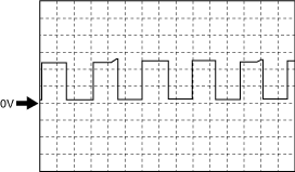
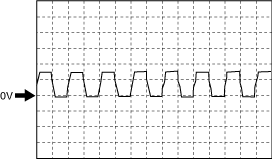
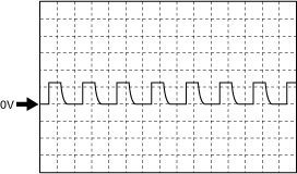
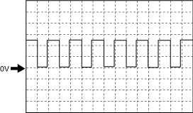
Revolution sensor signal
Wave pattern (reference)
am3zzw00024010
|
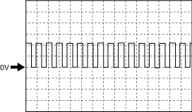
-
PCM terminals
-
• 1AC(+)—body ground(–)
-
Oscilloscope setting
-
• 2 V/DIV (Y), 5 ms/DIV (X), DC range
-
Vehicle condition
-
• Idle (after warm up)
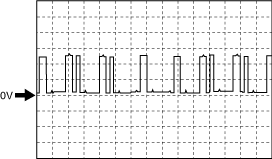
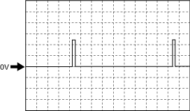
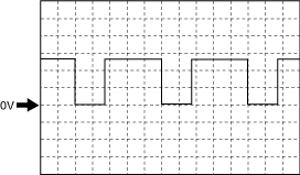
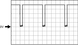
am3zzw00024011
|
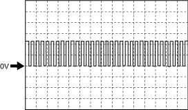
-
PCM terminals
-
• 1AC(+)—body ground(–)
-
Oscilloscope setting
-
• 2 V/DIV (Y), 5 ms/DIV (X), DC range
-
Vehicle condition
-
• Racing (Engine speed: 2,000 rpm)
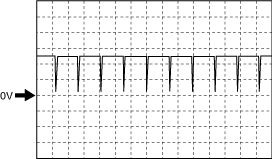
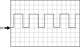
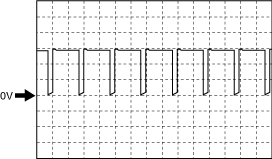
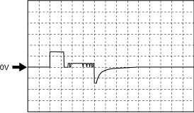
Electric variable valve timing motor (rotation direction) signal
adejjw00007909
|
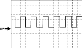
-
PCM terminals
-
• 1BN(+)—body ground(–)
-
Oscilloscope setting
-
• 2 V/DIV (Y), 5 ms/DIV (X), DC range
-
Vehicle condition
-
• Idle (after warm up)
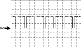
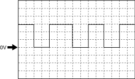
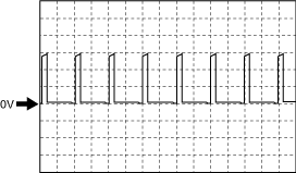
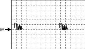
Electric variable valve timing motor (rotation pulse) signal
adejjw00007910
|
-
PCM terminals
-
• 1BM(+)—body ground(–)
-
Oscilloscope setting
-
• 2 V/DIV (Y), 5 ms/DIV (X), DC range
-
Vehicle condition
-
• Idle (after warm up)
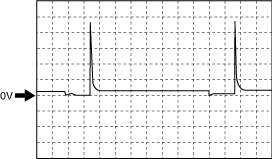
Exhaust CMP signal
adejjw00007911
|
-
PCM terminals
-
• 1BZ(+)—body ground(–)
-
Oscilloscope setting
-
• 2 V/DIV (Y), 20 ms/DIV (X), DC range
-
Vehicle condition
-
• Idle (after warm up)
Intake CMP signal
adejjw00007911
|
-
PCM terminals
-
• 1BT(+)—body ground(–)
-
Oscilloscope setting
-
• 2 V/DIV (Y), 20 ms/DIV (X), DC range
-
Vehicle condition
-
• Idle (after warm up)
CKP signal
adejjw00007912
|
-
PCM terminals
-
• 1F(+)—body ground(–)
-
Oscilloscope setting
-
• 2 V/DIV (Y), 1 ms/DIV (X), DC range
-
Vehicle condition
-
• Idle (after warm up)
Electric variable valve timing driver (diagnostic) signal
adejjw00007913
|
-
PCM terminals
-
• 1AD(+)—body ground(–)
-
Oscilloscope setting
-
• 2 V/DIV (Y), 100 ms/DIV (X), DC range
-
Vehicle condition
-
• Idle (after warm up)
Generator output voltage
adejjw00007914
|
-
PCM terminals
-
• 1AG+)—body ground(–)
-
Oscilloscope setting
-
• 5 V/DIV (Y), 2 ms/DIV (X), DC range
-
Vehicle condition
-
• Idle after warm up
Purge control
adejjw00007915
|

-
PCM terminals
-
• 1AW(+)—body ground(–)
-
Oscilloscope setting
-
• 10 V/DIV (Y), 50 ms/DIV (X), DC range
-
Vehicle condition
-
• Racing (Engine speed: 2,000 rpm)
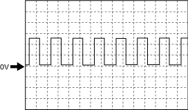
IGT1, IGT2, IGT3, IGT4 control
adejjw00007916
|
-
PCM terminals
-
• IGT1 (ignition coil No.1): 1BC(+)—body ground(–)• IGT2 (ignition coil No.2): 1BI(+)—body ground(–)• IGT3 (ignition coil No.3): 1BO(+)—body ground(–)• IGT4 (ignition coil No.4): 1BU(+)—body ground(–)
-
Oscilloscope setting
-
• 2 V/DIV (Y), 20 ms/DIV (X), DC range
-
Vehicle condition
-
• Idle after warm up
Hydraulic variable valve timing control signal
adejjw00007917
|
-
PCM terminals
-
• 1CO(+)—body ground(–)
-
Oscilloscope setting
-
• 5 V/DIV (Y), 1 ms/DIV (X), DC range
-
Vehicle condition
-
• Racing (Engine speed: 2,000 rpm)
Engine oil control signal
adejjw00002085
|
-
PCM terminals
-
• 1CK(+)—body ground(–)
-
Oscilloscope setting
-
• 5 V/DIV (Y), 1 ms/DIV (X), DC range
-
Vehicle condition
-
• Idle after warm up
Electric variable valve timing control signal
adejjw00007919
|

-
PCM terminals
-
• 1BV+)—body ground(–)
-
Oscilloscope setting
-
• 2 V/DIV (Y), 2 ms/DIV (X), DC range
-
Vehicle condition
-
• Idle after warm up
Generator field coil control signal
adejjw00007920
|
-
PCM terminals
-
• 1BP(+)—body ground(–)
-
Oscilloscope setting
-
• 1 V/DIV (Y), 2 ms/DIV (X), DC range
-
Vehicle condition
-
• Idle after warm up
A/F sensor heater control signal
adejjw00002081
|
-
PCM terminals
-
• 1CB(+)—body ground(–)
-
Oscilloscope setting
-
• 5 V/DIV (Y), 2 ms/DIV (X), DC range
-
Vehicle condition
-
• Idle after warm up
Drive-by-wire control (+) signal
-
Note
-
• The wave pattern is either type A or B depending on the PCM specifications.
Type A
am3zzw00012795
|
-
PCM terminals
-
• 1CQ(+)—1CR(–)
-
Oscilloscope setting
-
• 5 V/DIV (Y), 1 ms/DIV (X), DC range
-
Vehicle condition
-
• Idle after warm up
Type B
ac3jjw00004192
|
-
PCM terminals
-
• 1CQ(+)—1CR(–)
-
Oscilloscope setting
-
• 5 V/DIV (Y), 1 ms/DIV (X), DC range
-
Vehicle condition
-
• Idle after warm up
Fuel injection control (-) signal
adejjw00002082
|

-
PCM terminals
-
• Fuel Injection No.1: 1DH(+)—body ground(–)• Fuel Injection No.2: 1CZ(+)—body ground(–)• Fuel Injection No.3: 1CV(+)—body ground(–)• Fuel Injection No.4: 1DD(+)—body ground(–)
-
Oscilloscope setting
-
• 50 V/DIV (Y), 5 ms/DIV (X), DC range
-
Vehicle condition
-
• Idle after warm up
Fuel injection control (+) signal
adejjw00002083
|
-
PCM terminals
-
• Fuel Injection No.1: 1DG(+)—body ground(–)• Fuel Injection No.2: 1CY(+)—body ground(–)• Fuel Injection No.3: 1CU(+)—body ground(–)• Fuel Injection No.4: 1DC(+)—body ground(–)
-
Oscilloscope setting
-
• 50 V/DIV (Y), 5 ms/DIV (X), DC range
-
Vehicle condition
-
• Idle after warm up
High pressure fuel pump control (+) signal
adejjw00007925
|
-
PCM terminals
-
• 1DI(+)—body ground(–)
-
Oscilloscope setting
-
• 10 V/DIV (Y), 5 ms/DIV (X), DC range
-
Vehicle condition
-
• Idle after warm up
High pressure fuel pump control (-) signal
ac5uuw00004803
|
-
PCM terminals
-
• 1DJ(+)—body ground(–)
-
Oscilloscope setting
-
• 10 V/DIV (Y), 5 ms/DIV (X), DC range
-
Vehicle condition
-
• Idle after warm up
HO2S heater control signal
adejjw00007927
|
-
PCM terminals
-
• 2BJ(+)—body ground(–)
-
Oscilloscope setting
-
• 5 V/DIV (Y), 50 ms/DIV (X), DC range
-
Vehicle condition
-
• Idle (immediately after starting engine)
Fuel pump control signal
ac5jjw00009364
|
-
PCM terminals
-
• 2D(+)—body ground(–)
-
Oscilloscope setting
-
• 5 V/DIV (Y), 2 ms/DIV (X), DC range
-
Vehicle condition
-
• Idle after warm up
Fuel pump control module (diagnostic) signal
adejjw00002084
|
-
PCM terminals
-
• 2AX(+)—body ground(–)
-
Oscilloscope setting
-
• 2 V/DIV (Y), 20 ms/DIV (X), DC range
-
Vehicle condition
-
• Idle after warm up