DTC P0172:00 [PCM (SKYACTIV-G (WITHOUT CYLINDER DEACTIVATION (US)))]
DTC P0172:00 [PCM (SKYACTIV-G (WITHOUT CYLINDER DEACTIVATION (US)))]
SM2565578
id0102t49343u5
-
Note
-
• To determine the malfunctioning part, proceed with the diagnostics from “Function Inspection Using M-MDS”.
Details On DTCs
|
Description |
Fuel trim system too rich |
|
|---|---|---|
|
Detection condition
|
Determination conditions
|
• Any one of the following conditions is met:
|
|
Preconditions
|
• Engine coolant temperature: 0—45 °C {32—113 °F}, 60 °C {140 °F} or more *1
*1: Standard can be verified by displaying PIDs using M-MDS
|
|
|
Malfunction determination period
|
• 10 s or 20 s period
|
|
|
Drive cycle
|
• 2
|
|
|
Self test type
|
• CMDTC self test
|
|
|
Sensor used
|
• A/F sensor
|
|
|
Fail-safe function
|
• Not applicable
|
|
|
Vehicle status when DTCs are output
|
• Not applicable
|
|
|
Possible cause
|
• Erratic signal to PCM
• High-pressure side fuel delivery system malfunction
• Low-pressure side fuel delivery system malfunction
• Fuel injector malfunction
• Improper operation of purge control system
• MAF sensor malfunction
• MAP sensor malfunction
• Improper operation of electric variable valve timing control system
• Improper operation of hydraulic variable valve timing control system
• A/F sensor malfunction
• Penetration of fuel into engine oil (excessive dilution)
• PCM malfunction
|
|
System Wiring Diagram
• Not applicable
Function Explanation (DTC Detection Outline)
• The PCM detects the oxygen concentration in the exhaust gas from the A/F sensor signal and performs fuel injection amount feedback to maintain the optimum air/fuel ratio. If a condition in which the feedback correction amount is small (fuel injection amount being decreased) continues for the specified time, a feedback correction amount malfunction is determined, and a DTC is stored. The feedback correction amount has a “Fuel feedback correction amount” for the air/fuel ratio and a “Fuel learning correction amount” for fuel injector deterioration over time.
• “Fuel feedback correction amount (SHRT_FUEL_TRIM)” and “Fuel learning correction amount (LONG_FUEL_TRIM)” can be verified from the M-MDS PID item.
1. The sum of the fuel feedback correction amount (SHRT_FUEL_TRIM) and the fuel learning correction amount (LONG_FUEL_TRIM) is the specified value ( −31 %) or less, and 10 s or more have elapsed with the fuel learning correction amount (LONG_FUEL_TRIM) at the specified value ( −15 %) or less. Engine coolant temperature: 0—45 °C {32—113 °F}, 60 °C {140 °F} or more
am3zzw00034723
|

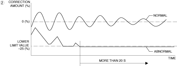
2. The fuel feedback correction amount reaches the lower limit ( −25% or less) for 20 s or more. Engine coolant temperature: 0—45 °C {32—113 °F}, 60 °C {140 °F} or more
am3zzw00034224
|
Repeatability Verification Procedure
1. Warm up the engine to allow the engine coolant temperature to reach 80 °C {176 °F} or more.
2. Start the engine and leave it idling for 1 min.
-
Note
-
• Match the engine coolant temperature in the recorded freeze frame data/snapshot data, the vehicle speed, and engine speed values to the best extent possible while driving the vehicle.
3. Try to reproduce the malfunction by driving the vehicle for 5 min based on the values in the freeze frame data/snapshot data.
PID Item/Simulation Item Used In Diagnosis
PID/DATA monitor item table
|
PIDs |
Reference |
|---|---|
|
APP_RELAT
|
|
|
ECT
|
|
|
ECT_VOLT
|
|
|
PRG_DUTY
|
|
|
FDIL_JD
|
|
|
FUEL_PUMP_REQ
|
|
|
FUEL_PRES
|
|
|
IAT2
|
|
|
MAF
|
|
|
MAP
|
|
|
MAP_VOLT
|
|
|
A/F_SEN_CUR
|
|
|
TP_RELAT
|
|
|
VLV_TIMING_ACT_EX
|
|
|
VLV_TIMING_DSD_EX
|
|
|
VLV_TIMING_ACT_IN
|
|
|
VLV_TIMING_DSD_IN
|
Simulation item table
|
Simulation items |
Reference |
|---|---|
|
FUEL_PUMP_REQ
|
|
|
INJ
|
Function Inspection Using M-MDS
|
Step |
Inspection |
Results |
Action |
|---|---|---|---|
|
1
|
PURPOSE: VERIFY RELATED REPAIR INFORMATION OR SERVICE INFORMATION AVAILABILITY
• Verify related Service Bulletins, on-line repair information, or Service Information availability.
• Is any related Information available?
|
Yes
|
Perform repair or diagnosis according to the available information.
• If the vehicle is not repaired, go to the next step.
|
|
No
|
Go to the next step.
|
||
|
2
|
PURPOSE: IDENTIFY TRIGGER DTC FOR FREEZE FRAME DATA
• Is the DTC P0172:00 on freeze frame data?
|
Yes
|
Go to the next step.
|
|
No
|
Go to the troubleshooting procedure for DTC on freeze frame data.
|
||
|
3
|
PURPOSE: RECORD VEHICLE STATUS WHEN DTC WAS DETECTED TO UTILIZE WITH REPEATABILITY VERIFICATION
• Record the freeze frame data/snapshot data.
|
—
|
Go to the next step.
|
|
4
|
PURPOSE: VERIFY IF INPUT SIGNAL TO PCM AFFECTS FUEL INJECTION
• Start the engine.
• Access the following PIDs using the M-MDS: (See PID/DATA MONITOR INSPECTION.)
• Is there any signal that is far out of specification? (See PID/DATA MONITOR TABLE [PCM (SKYACTIV-G (US))].)
|
Yes
|
Inspect the suspected sensor and related wiring harness.
• If there is any malfunction:
• If there is no malfunction:
|
|
No
|
Go to the next step.
|
||
|
5
|
PURPOSE: VERIFY CONNECTOR CONNECTIONS
• Start the engine.
• Access the following PIDs using the M-MDS: (See PID/DATA MONITOR INSPECTION.)
• When the following parts are shaken, does the PID value include a PID item which has changed?
|
Yes
|
Repair or replace the applicable connector parts.
Go to Troubleshooting Diagnostic Procedure to perform the repair completion verification.
|
|
No
|
Go to the next step.
|
||
|
6
|
PURPOSE: VERIFY FUEL PRESSURE (HIGH-SIDE) MALFUNCTION
• Switch the ignition off.
• Reconnect all disconnected connectors.
• Start the engine and warm it up completely.
• Access the FUEL_PRES PID using the M-MDS. (See PID/DATA MONITOR INSPECTION.)
• Is the FUEL_PRES PID value approx. 10 MPa {102 kgf/cm2, 1450 psi}?
|
Yes
|
Go to the next step.
|
|
No
|
FUEL_PRES PID value is lower than 10 MPa {102 kgf/cm2, 1450 psi}:
• Go to Troubleshooting Diagnostic Procedure to perform the procedure from Step 1.
FUEL_PRES PID value is higher than 10 MPa {102 kgf/cm2, 1450 psi}:
• Go to Step 8.
|
||
|
7
|
PURPOSE: VERIFY FUEL PRESSURE (LOW-SIDE) MALFUNCTION
• Bleed the remaining pressure in the fuel line using the following procedure.
• Switch the ignition off.
• Install the fuel pump relay.
• Switch the ignition ON (engine off).
• Display PID FUEL_PRES and simulation item FUEL_PUMP_REQ using the M-MDS. (See PID/DATA MONITOR INSPECTION.) (See SIMULATION INSPECTION.)
• Turn simulation item FUEL_PUMP_REQ on.
• Is the FUEL_PRES PID value 475—555 kPa {4.85—5.65 kgf/cm2, 68.9—80.4 psi}?
|
Yes
|
Go to the next step.
|
|
No
|
Go to Troubleshooting Diagnostic Procedure to perform the procedure from Step 1.
|
||
|
8
|
PURPOSE: VERIFY IF MALFUNCTION CAUSED BY FUEL INJECTOR IMPROPER OPERATION
• Switch the ignition off.
• Reconnect all disconnected connectors.
• Start the engine and idle it.
• Access the following simulation items using the M-MDS: (See SIMULATION INSPECTION.)
• Turn each fuel injector from on to off using the simulation items.
• Does the vibration during idling worsen?
|
Yes
|
Go to the next step.
|
|
No
|
Go to Troubleshooting Diagnostic Procedure to perform the procedure from Step 3.
|
||
|
9
|
PURPOSE: VERIFY IF MALFUNCTION CAUSED BY PURGE SOLENOID VALVE IMPROPER OPERATION
• Start the engine and idle it.
• Access the PRG_DUTY PID using the M-MDS. (See PID/DATA MONITOR INSPECTION.)
• Is the PRG_DUTY PID value normal?
|
Yes
|
Go to the next step.
|
|
No
|
Go to Troubleshooting Diagnostic Procedure to perform the procedure from Step 4.
|
||
|
10
|
PURPOSE: VERIFY MAF SENSOR
• Start the engine and idle it.
• Access the MAF PID using the M-MDS. (See PID/DATA MONITOR INSPECTION.)
• Is the MAF PID value normal?
|
Yes
|
Go to the next step.
|
|
No
|
Go to Troubleshooting Diagnostic Procedure to perform the procedure from Step 5.
|
||
|
11
|
PURPOSE: VERIFY MAP SENSOR
• Start the engine and idle it.
• Access the following PIDs using the M-MDS: (See PID/DATA MONITOR INSPECTION.)
• Are all items normal?
|
Yes
|
Go to the next step.
|
|
No
|
Go to Troubleshooting Diagnostic Procedure to perform the procedure from Step 7.
|
||
|
12
|
PURPOSE: VERIFY INTAKE VALVE TIMING
• Start the engine and idle it.
• Access the following PIDs using the M-MDS: (See PID/DATA MONITOR INSPECTION.)
• Depress the accelerator pedal to increase the engine speed.
• Does the monitor value of the PID item VLV_TIMING_ACT_IN conform to the VLV_TIMING_DSD_IN PID value?
|
Yes
|
Go to the next step.
|
|
No
|
Go to Troubleshooting Diagnostic Procedure to perform the procedure from Step 8.
|
||
|
13
|
PURPOSE: VERIFY EXHAUST VALVE TIMING
• Start the engine and idle it.
• Access the following PIDs using the M-MDS: (See PID/DATA MONITOR INSPECTION.)
• Perform the following:
• Does the monitor value of the PID item VLV_TIMING_ACT_EX conform to the VLV_TIMING_DSD_EX PID value?
|
Yes
|
Go to the next step.
|
|
No
|
Go to Troubleshooting Diagnostic Procedure to perform the procedure from Step 11.
|
||
|
14
|
PURPOSE: VERIFY A/F SENSOR
• Access the A/F_SEN_CUR PID using the M-MDS. (See PID/DATA MONITOR INSPECTION.)
• Is the A/F_SEN_CUR PID value normal?
|
Yes
|
Go to the next step.
|
|
No
|
Go to Troubleshooting Diagnostic Procedure to perform the procedure from Step 12.
|
||
|
15
|
PURPOSE: VERIFY IF MALFUNCTION IS CAUSED BY FUEL PENETRATION INTO ENGINE OIL
• Access the FDIL_JD PID using the M-MDS. (See PID/DATA MONITOR INSPECTION.)
• Is the engine oil diluted due to fuel penetration?
|
Yes
|
Replace the engine oil with genuine motor oil.
Go to Troubleshooting Diagnostic Procedure to perform the repair completion verification.
|
|
No
|
Go to the next step.
|
||
|
16
|
PURPOSE: INSPECT FOR OTHER RELATED DTCs
• Perform the DTC inspection for the PCM. (See DTC INSPECTION.)
• Are any other DTCs displayed?
|
Yes
|
Repair the malfunctioning location according to the applicable DTC troubleshooting.
Go to Troubleshooting Diagnostic Procedure to perform the procedure from Step 1.
|
|
No
|
Go to Troubleshooting Diagnostic Procedure to perform the procedure from Step 1.
|
Troubleshooting Diagnostic Procedure
Intention of troubleshooting procedure
• Step 1—3
-
― Perform a fuel injector control system inspection.
• Step 4
-
― Perform an emission system parts inspection.
• Step 5—7
-
― Perform an intake air system parts inspection.
• Step 8—11
-
― Perform a valve timing inspection.
• Step 12
-
― Perform an exhaust system parts inspection.
• Repair completion verification
-
― Verify that the primary malfunction is resolved and there are no other malfunctions.
|
Step |
Inspection |
Results |
Action |
|---|---|---|---|
|
1
|
PURPOSE: INSPECT FUEL PUMP CONTROL MODULE FOR MALFUNCTION
• Inspect the applicable part. (See FUEL PUMP CONTROL MODULE INSPECTION [SKYACTIV-G (WITHOUT CYLINDER DEACTIVATION (US))].)
• Is the part normal?
|
Yes
|
Go to the next step.
|
|
No
|
Repair or replace the malfunctioning location and perform the repair completion verification.
|
||
|
2
|
PURPOSE: INSPECT FUEL PUMP UNIT FOR MALFUNCTION
• Inspect the applicable part. (See FUEL PUMP UNIT INSPECTION [SKYACTIV-G (WITHOUT CYLINDER DEACTIVATION (US))].)
• Is the part normal?
|
Yes
|
Go to the next step.
|
|
No
|
Repair or replace the malfunctioning location and perform the repair completion verification.
|
||
|
3
|
PURPOSE: INSPECT FUEL INJECTOR FOR MALFUNCTION
• Inspect the applicable part. (See FUEL INJECTOR INSPECTION [SKYACTIV-G (WITHOUT CYLINDER DEACTIVATION (US))].)
• Is the part normal?
|
Yes
|
Go to the next step.
|
|
No
|
Repair or replace the malfunctioning location and perform the repair completion verification.
|
||
|
4
|
PURPOSE: INSPECT PURGE SOLENOID VALVE FOR MALFUNCTION
• Inspect the applicable part. (See PURGE SOLENOID VALVE INSPECTION [SKYACTIV-G (WITHOUT CYLINDER DEACTIVATION (US))].)
• Is the part normal?
|
Yes
|
Go to the next step.
|
|
No
|
Repair or replace the malfunctioning location and perform the repair completion verification.
|
||
|
5
|
PURPOSE: INSPECT MAF SENSOR FOR MALFUNCTION
• Inspect the applicable part. (See MASS AIR FLOW (MAF) SENSOR INSPECTION [SKYACTIV-G (WITHOUT CYLINDER DEACTIVATION (US))].)
• Is the part normal?
|
Yes
|
Go to the next step.
|
|
No
|
Repair or replace the malfunctioning location and perform the repair completion verification.
|
||
|
6
|
PURPOSE: INSPECT AIR CLEANER ELEMENT FOR MALFUNCTION
• Remove the air cleaner element with the engine is running. (See AIR CLEANER ELEMENT REMOVAL/INSTALLATION [SKYACTIV-G (WITHOUT CYLINDER DEACTIVATION (US))].)
• Does the engine speed increase?
|
Yes
|
Inspect the air cleaner element.
• If there is any malfunction:
• If there is no malfunction:
|
|
No
|
Go to the next step.
|
||
|
7
|
PURPOSE: INSPECT MAP SENSOR FOR MALFUNCTION
• Inspect the applicable part. (See MANIFOLD ABSOLUTE PRESSURE (MAP) SENSOR INSPECTION [SKYACTIV-G (WITHOUT CYLINDER DEACTIVATION (US))].)
• Is the part normal?
|
Yes
|
Go to the next step.
|
|
No
|
Repair or replace the malfunctioning location and perform the repair completion verification.
|
||
|
8
|
PURPOSE: INSPECT ELECTRIC VARIABLE VALVE TIMING DRIVER FOR MALFUNCTION
• Inspect the applicable part. (See ELECTRIC VARIABLE VALVE TIMING MOTOR/DRIVER INSPECTION [SKYACTIV-G (WITHOUT CYLINDER DEACTIVATION (US))].)
• Is the part normal?
|
Yes
|
Go to the next step.
|
|
No
|
Repair or replace the malfunctioning location and perform the repair completion verification.
|
||
|
9
|
PURPOSE: INSPECT ELECTRIC VARIABLE VALVE TIMING MOTOR FOR MALFUNCTION
• Inspect the applicable part. (See ELECTRIC VARIABLE VALVE TIMING MOTOR/DRIVER INSPECTION [SKYACTIV-G (WITHOUT CYLINDER DEACTIVATION (US))].)
• Is the part normal?
|
Yes
|
Go to the next step.
|
|
No
|
Repair or replace the malfunctioning location and perform the repair completion verification.
|
||
|
10
|
PURPOSE: INSPECT ELECTRIC VARIABLE VALVE TIMING ACTUATOR FOR MALFUNCTION
• Inspect the applicable part. (See ELECTRIC VARIABLE VALVE TIMING ACTUATOR INSPECTION [SKYACTIV-G (WITHOUT CYLINDER DEACTIVATION (US))].)
• Is the part normal?
|
Yes
|
Go to the next step.
|
|
No
|
Repair or replace the malfunctioning location and perform the repair completion verification.
|
||
|
11
|
PURPOSE: INSPECT OCV FOR MALFUNCTION
• Inspect the applicable part. (See OIL CONTROL VALVE (OCV) INSPECTION [SKYACTIV-G (WITHOUT CYLINDER DEACTIVATION (US))].)
• Is the part normal?
|
Yes
|
Go to the next step.
|
|
No
|
Repair or replace the malfunctioning location and perform the repair completion verification.
|
||
|
12
|
PURPOSE: INSPECT A/F SENSOR FOR MALFUNCTION
• Inspect the applicable part. (See AIR FUEL RATIO (A/F) SENSOR INSPECTION [SKYACTIV-G (WITHOUT CYLINDER DEACTIVATION (US))].)
• Is the part normal?
|
Yes
|
Go to the next step.
|
|
No
|
Repair or replace the malfunctioning location and perform the repair completion verification.
|
||
|
Repair completion verification
|
PURPOSE: VERIFY THAT VEHICLE IS REPAIRED
• Install/connect the part removed/disconnected during the troubleshooting procedure.
• Clear the DTC recorded in the memory. (See CLEARING DTC.)
• Replicate the vehicle conditions at the time the DTC was detected using the following procedure.
• Perform the DTC inspection for the PCM. (See DTC INSPECTION.)
• Is the same Pending DTC present?
|
Yes
|
Refer to the controller area network (CAN) malfunction diagnosis flow to inspect for a CAN communication error.
If the CAN communication is normal, perform the diagnosis from Step 1.
• If the malfunction recurs, replace the PCM. (See PCM REMOVAL/INSTALLATION [SKYACTIV-G (WITHOUT CYLINDER DEACTIVATION (US))].)
|
|
No
|
DTC troubleshooting completed.
|