DTC P0462:00 [PCM (SKYACTIV-G (US))]
DTC P0462:00 [PCM (SKYACTIV-G (US))]
SM2565533
id0102t43016u0
Outline
|
System malfunction location |
Fuel gauge sender unit circuit low input |
||||
|---|---|---|---|---|---|
|
Detection condition
|
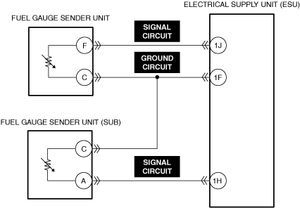
• The PCM monitors the fuel level signal and fuel gauge sender unit output voltage from the instrument cluster. If the PCM detects that the fuel level, fuel gauge sender unit, or fuel gauge sender unit (SUB) output voltage is too low, the PCM determines that the fuel gauge sender unit or fuel gauge sender unit (SUB) circuit has a malfunction.
|
||||
|
Fail-safe
|
• Not applicable
|
||||
|
Possible cause
|
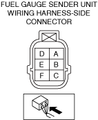
• Fuel gauge sender unit connector or terminals malfunction
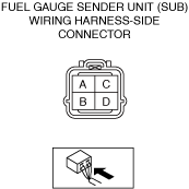
• Fuel gauge sender unit (SUB) connector or terminals malfunction
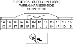
• Electrical supply unit (ESU) connector or terminals malfunction
• Short to ground in fuel gauge sender unit signal circuit
• Short to ground in fuel gauge sender unit (SUB) signal circuit
• Short circuit in fuel gauge sender unit signal circuit and ground circuit
• Short circuit in fuel gauge sender unit (SUB) signal circuit and ground circuit
• Fuel gauge sender unit malfunction
• Fuel gauge sender unit (SUB) malfunction
• Electrical supply unit (ESU) malfunction
• Instrument cluster malfunction
• PCM malfunction
|
||||
 |
|||||
 |
 |
||||
 |
|||||
Diagnostic Procedure
|
Step |
Inspection |
Results |
Action |
|---|---|---|---|
|
1
|
RECORD VEHICLE STATUS WHEN DTC WAS DETECTED TO UTILIZE WITH REPEATABILITY VERIFICATION
• Record the freeze frame data/snapshot data.
|
—
|
Go to the next step.
|
|
2
|
VERIFY RELATED REPAIR INFORMATION OR SERVICE INFORMATION AVAILABILITY
• Verify related Service Bulletins, on-line repair information, or Service Information availability.
• Is any related Information available?
|
Yes
|
Perform repair or diagnosis according to the available information.
• If the vehicle is not repaired, go to the next step.
|
|
No
|
Go to the next step.
|
||
|
3
|
INSPECT FUEL GAUGE SENDER UNIT CONNECTOR FOR MALFUNCTION
• Inspect the applicable connector and terminal. (See CONNECTOR INSPECTION.)
• Are the connector and terminal normal?
|
Yes
|
Go to the next step.
|
|
No
|
Repair or replace the malfunctioning location and perform the repair completion verification.
|
||
|
4
|
INSPECT FUEL GAUGE SENDER UNIT (SUB) CONNECTOR FOR MALFUNCTION
• Inspect the applicable connector and terminal. (See CONNECTOR INSPECTION.)
• Are the connector and terminal normal?
|
Yes
|
Go to the next step.
|
|
No
|
Repair or replace the malfunctioning location and perform the repair completion verification.
|
||
|
5
|
INSPECT ELECTRICAL SUPPLY UNIT (ESU) CONNECTOR FOR MALFUNCTION
• Inspect the applicable connector and terminal. (See CONNECTOR INSPECTION.)
• Are the connector and terminal normal?
|
Yes
|
Go to the next step.
|
|
No
|
Repair or replace the malfunctioning location and perform the repair completion verification.
|
||
|
6
|
INSPECT FUEL GAUGE SENDER UNIT SIGNAL CIRCUIT FOR SHORT TO GROUND
• Inspect the applicable circuit for a short to ground. (See CIRCUIT INSPECTION.)
• Is the circuit normal?
|
Yes
|
Go to the next step.
|
|
No
|
Repair or replace the malfunctioning location and perform the repair completion verification.
|
||
|
7
|
INSPECT FUEL GAUGE SENDER UNIT (SUB) SIGNAL CIRCUIT FOR SHORT TO GROUND
• Inspect the applicable circuit for a short to ground. (See CIRCUIT INSPECTION.)
• Is the circuit normal?
|
Yes
|
Go to the next step.
|
|
No
|
Repair or replace the malfunctioning location and perform the repair completion verification.
|
||
|
8
|
INSPECT FUEL GAUGE SENDER UNIT SIGNAL CIRCUIT AND GROUND CIRCUIT FOR SHORT CIRCUIT
• Inspect the applicable circuits for a short circuit. (See CIRCUIT INSPECTION.)
• Is the circuit normal?
|
Yes
|
Go to the next step.
|
|
No
|
Repair or replace the malfunctioning location and perform the repair completion verification.
|
||
|
9
|
INSPECT FUEL GAUGE SENDER UNIT (SUB) SIGNAL CIRCUIT AND GROUND CIRCUIT FOR SHORT CIRCUIT
• Inspect the applicable circuits for a short circuit. (See CIRCUIT INSPECTION.)
• Is the circuit normal?
|
Yes
|
Go to the next step.
|
|
No
|
Repair or replace the malfunctioning location and perform the repair completion verification.
|
||
|
10
|
INSPECT FUEL GAUGE SENDER UNIT FOR MALFUNCTION
2WD
• Inspect the fuel gauge sender unit . (See FUEL GAUGE SENDER UNIT INSPECTION [(US)].)
AWD
• Inspect the fuel gauge sender unit or fuel gauge sender unit (SUB). (See FUEL GAUGE SENDER UNIT INSPECTION [(US)].)
• Is the part normal?
|
Yes
|
Go to the next step.
|
|
No
|
Repair or replace the malfunctioning location and perform the repair completion verification.
|
||
|
11
|
INSPECT ELECTRICAL SUPPLY UNIT (ESU) FOR MALFUNCTION
• Inspect the applicable part. (See ELECTRICAL SUPPLY UNIT (ESU) INSPECTION.)
• Is the part normal?
|
Yes
|
Go to the next step.
|
|
No
|
Repair or replace the malfunctioning location and perform the repair completion verification.
|
||
|
12
|
INSPECT INSTRUMENT CLUSTER FOR MALFUNCTION
• Inspect the applicable part. (See INSTRUMENT CLUSTER INSPECTION [(US)].)
• Is the part normal?
|
Yes
|
Go to the next step.
|
|
No
|
Repair or replace the malfunctioning location and perform the repair completion verification.
|
||
|
Repair completion verification 1
|
VERIFY THAT VEHICLE IS REPAIRED
• Install/connect the part removed/disconnected during the troubleshooting procedure.
• Clear the DTC recorded in the memory. (See CLEARING DTC.)
• Replicate the vehicle conditions at the time the DTC was detected using the following procedure.
• Perform the DTC inspection for the PCM. (See DTC INSPECTION.)
• Is the same Pending DTC present?
|
Yes
|
Refer to the controller area network (CAN) malfunction diagnosis flow to inspect for a CAN communication error.
If the CAN communication is normal, perform the diagnosis from Step 1.
• If the malfunction recurs, replace the PCM, then go to the next step. (See PCM REMOVAL/INSTALLATION [SKYACTIV-G (WITH CYLINDER DEACTIVATION (US))].) (See PCM REMOVAL/INSTALLATION [SKYACTIV-G (WITHOUT CYLINDER DEACTIVATION (US))].)
|
|
No
|
Go to the next step.
|
||
|
Repair completion verification 2
|
VERIFY IF OTHER DTCs DISPLAYED
• Perform the DTC inspection. (See DTC INSPECTION.)
• Are any other DTCs displayed?
|
Yes
|
Repair the malfunctioning location according to the applicable DTC troubleshooting.
|
|
No
|
DTC troubleshooting completed.
|