ELECTRICAL SUPPLY UNIT (ESU) REMOVAL/INSTALLATION
ELECTRICAL SUPPLY UNIT (ESU) REMOVAL/INSTALLATION
SM2336727
id094000003200
-
Caution
-
• When replacing the electrical supply unit (ESU), perform the configuration to assure that the system operates correctly. (See CONFIGURATION.)
4SD
1.Disconnect the negative battery terminal. (See NEGATIVE BATTERY TERMINAL DISCONNECTION/CONNECTION [(US)].)
2.Remove the following parts:
- (1)Trunk covering (See TRUNK COVERING REMOVAL/INSTALLATION.)
- (2)Trunk board (See TRUNK BOARD REMOVAL/INSTALLATION [(US)].)
- (3)Trunk end trim (See TRUNK END TRIM REMOVAL/INSTALLATION.)
3.Partially peel the trunk side trim (LH). (See TRUNK SIDE TRIM REMOVAL/INSTALLATION [(US)].)
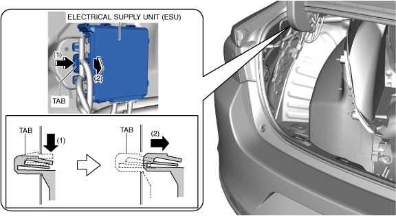
4.While pressing the electrical supply unit (ESU) tab in the direction of arrow (1) shown in the figure, pull the electrical supply unit (ESU) in the direction of arrow (2) and detach the electrical supply unit (ESU) tab from the body.
am3zzw00022219
|
5.Pull the electrical supply unit (ESU) in the direction of the arrow shown in the figure and detach the hook from the body.
am3zzw00028090
|

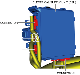
6.Disconnect the connectors.
am3zzw00022221
|
7.Remove the electrical supply unit (ESU).
8.Install in the reverse order of removal.
9.If the electrical supply unit (ESU) is replaced, perform the following procedure:
- (1)Perform manual configuration using the following procedure.
-
- 1)Connect the M-MDS to the DLC-2.
- 2)Switch the ignition ON (engine off or on).
- 3)Perform vehicle identification.
- 4)Select [Configuration] using the M-MDS.
- 5)Select [ESU].
- 6)Perform manual configuration following the instructions on the screen.
- (2)Switch the ignition OFF.
- (3)Switch the ignition ON (engine off or on) and wait for 1 s or more, to complete the following.
-
-
• Automatic configuration of the electrical supply unit (ESU).
-
• Synchronization of the electrical supply unit (ESU) with the door-electrical supply unit and the body control module (BCM).
-
- (4)Clear the DTC. (See CLEARING DTC.)
5HB
1.Disconnect the negative battery terminal. (See NEGATIVE BATTERY TERMINAL DISCONNECTION/CONNECTION [(US)].)
2.Remove the following parts:
- (1)Rear package tray (See REAR PACKAGE TRAY REMOVAL/INSTALLATION.)
- (2)Trunk covering (See TRUNK COVERING REMOVAL/INSTALLATION.)
- (3)Trunk board (See TRUNK BOARD REMOVAL/INSTALLATION [(US)].)
- (4)Trunk end trim (See TRUNK END TRIM REMOVAL/INSTALLATION.)
- (5)Trunk side upper trim (LH) (See TRUNK SIDE UPPER TRIM REMOVAL/INSTALLATION.)
3.Partially peel the trunk side trim (LH). (See TRUNK SIDE TRIM REMOVAL/INSTALLATION [(US)].)
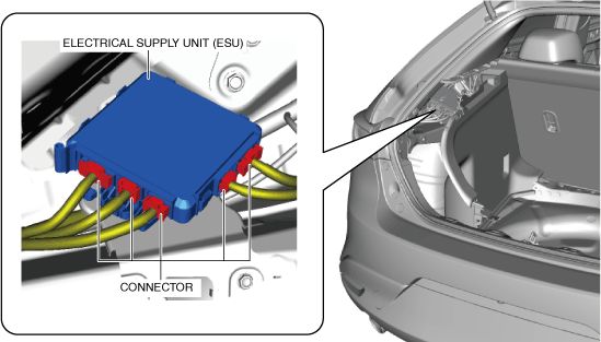
4.Disconnect the connectors.
am3zzw00022222
|
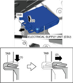
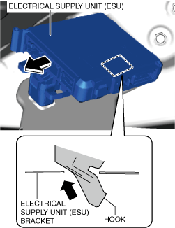
5.While pressing the electrical supply unit (ESU) tab in the direction of arrow (1) shown in the figure, pull the electrical supply unit (ESU) in the direction of arrow (2) and detach the electrical supply unit (ESU) tab from the electrical supply unit (ESU) bracket.
am3zzw00028091
|
6.Pull the electrical supply unit (ESU) in the direction of the arrow shown in the figure and detach the hook from the electrical supply unit (ESU) bracket.
am3zzw00028092
|
7.Remove the electrical supply unit (ESU).
8.Install in the reverse order of removal.
9.If the electrical supply unit (ESU) is replaced, perform the following procedure:
- (1)Perform manual configuration using the following procedure.
-
- 1)Connect the M-MDS to the DLC-2.
- 2)Switch the ignition ON (engine off or on).
- 3)Perform vehicle identification.
- 4)Select [Configuration] using the M-MDS.
- 5)Select [ESU].
- 6)Perform manual configuration following the instructions on the screen.
- (2)Switch the ignition OFF.
- (3)Switch the ignition ON (engine off or on) and wait for 1 s or more, to complete the following.
-
-
• Automatic configuration of the electrical supply unit (ESU).
-
• Synchronization of the electrical supply unit (ESU) with the door-electrical supply unit and the body control module (BCM).
-
- (4)Clear the DTC. (See CLEARING DTC.)