FUEL GAUGE SENDER UNIT REMOVAL/INSTALLATION [(US)]
FUEL GAUGE SENDER UNIT REMOVAL/INSTALLATION [(US)]
SM2515171
id0922000120x1
Special Service Tool (SST)
|
49 JP02 002
Lock ring wrench
|
 |
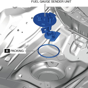
Replacement part
|
Packing
Quantity: 1
Location of use: Fuel gauge sender unit (sub)
|
-
Warning
-
• Fuel vapor is hazardous. It can very easily ignite, causing serious injury and damage. Always keep sparks and flames away from fuel.• Highly pressurized fuel may spray out if the fuel line is cut. Due to the following dangers occurring with a fuel spray, always complete the “Fuel Line Safety Procedure” to prevent the fuel from spraying.
-
― Fuel may cause irritation if it comes in contact with skin and eyes.― If fuel ignites and causes a fire, it may lead to serious injury or death, and damage to property and facilities.
• A person charged with static electricity could cause a fire or explosion, resulting in death or serious injury. Before performing work on the fuel system, discharge static electricity by touching the vehicle body. -
-
Caution
-
• Disconnecting/connecting the quick release connector without cleaning it may cause damage to the fuel pipe and quick release connector. Always clean the quick release connector joint area before disconnecting/connecting using a cloth or soft brush, and make sure that it is free of foreign material.
Fuel Gauge Sender Unit (Main)
-
Note
-
• For the fuel gauge sender unit removal/installation, refer to the fuel pump removal/installation because the fuel gauge sender unit is integrated with the fuel pump. (See FUEL PUMP UNIT REMOVAL/INSTALLATION [SKYACTIV-G (WITHOUT CYLINDER DEACTIVATION (US))].) (See FUEL PUMP UNIT REMOVAL/INSTALLATION [SKYACTIV-G (WITH CYLINDER DEACTIVATION (US))].)
Fuel Gauge Sender Unit (Sub)
1.Complete the “BEFORE SERVICE PRECAUTION”. (See BEFORE SERVICE PRECAUTION [SKYACTIV-G (WITH CYLINDER DEACTIVATION (US))].)
-
Warning
-
• If the fuel gauge level indicates 8/16 or more, refer to the [FUEL DRAINING PROCEDURE] and drain the fuel.(See FUEL DRAINING PROCEDURE [SKYACTIV-G (WITH CYLINDER DEACTIVATION (US))].)
2.Disconnect the negative battery terminal. (See NEGATIVE BATTERY TERMINAL DISCONNECTION/CONNECTION [(US)].)
3.Remove the rear seat cushion. (See REAR SEAT CUSHION REMOVAL/INSTALLATION.)
4.Remove the screws.
am3zzw00031789
|
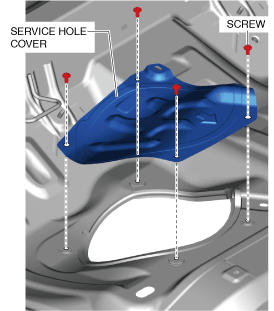
5.Remove the service hole cover.
6.Disconnect the connector.
am3zzw00036461
|
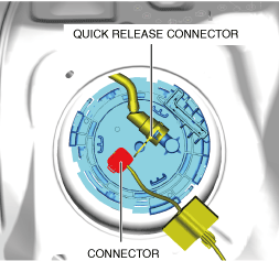
7.Disconnect the quick release connector. (See QUICK RELEASE CONNECTOR (EMISSION SYSTEM) REMOVAL/INSTALLATION [SKYACTIV-G (WITH CYLINDER DEACTIVATION (US))].)
8.Install the SST shown in the figure.
am3zzw00036847
|
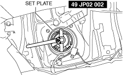
9.Remove the set plate component using the SST. (See Set plate component installation note.)
10.Remove the fuel gauge sender unit and packing.
am3zzw00036462
|
11.Install in the reverse order of removal.
12.Complete the “AFTER SERVICE PRECAUTION”. (See AFTER SERVICE PRECAUTION [SKYACTIV-G (WITH CYLINDER DEACTIVATION (US))].)
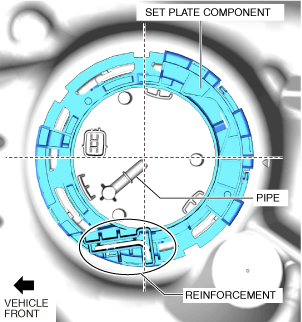
Set plate component installation note
1.Align the reinforcement part of the set plate component near the pipe area of the fuel pump unit as shown in the figure and assemble.
am3zzw00032848
|