DTC P2B61:00 [PCM (SKYACTIV-G (US))]
DTC P2B61:00 [PCM (SKYACTIV-G (US))]
SM2565530
id0102t41680u0
-
Note
-
• To determine the malfunctioning part, proceed with the diagnostics from “Function Inspection Using M-MDS”.
Details On DTCs
|
Description |
Coolant control valve circuit range/performance |
||
|---|---|---|---|
|
Detection condition
|
Determination conditions
|
• The coolant control valve control duty value is 89% or more for a continuous 2 s.
|
|
|
Preconditions
|
• Not applicable
|
||
|
Drive cycle
|
• 1
|
||
|
Self test type
|
• CMDTC self test
|
||
|
Sensor used
|
• Coolant control valve position sensor
|
||
|
Fail-safe function
|
• PCM restricts engine torque.
|
||
|
Vehicle status when DTCs are output
|
• Not applicable
|
||
|
Possible cause
|
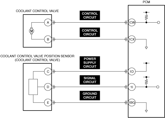
• Coolant control valve connector or terminals malfunction
• PCM connector or terminals malfunction
• Coolant control valve sticking, or foreign matter penetration
• Short to ground in coolant control valve control circuit
• Short to ground in any of the following coolant control valve position sensor circuits.
• Short circuit in coolant control valve control circuits
• Short circuit between any of the following coolant control valve position sensor circuits.
• Open circuit in coolant control valve control circuit
• Open circuit in any of the following coolant control valve position sensor circuits.
• Coolant control valve malfunction
• Coolant control valve position sensor malfunction
• PCM malfunction
|
||
 |
|||
 |
|||
 |
|||
Function Explanation (DTC Detection Outline)
• When a condition continues in which the engine coolant control valve does not operate even if the PCM applies maximum voltage to the valve, the PCM determines that the valve is stuck and stores a DTC.
Repeatability Verification Procedure
1.Warm up the engine to allow the engine coolant temperature to reach 50—95 °C {122—203 °F}.
-
Note
-
• The difference between PIDs ENG_COOL_VLV_POS_ACT and ENG_COOL_VLV_POS_COMD displayed the engine coolant control valve opening angle must be within 2 °.• Match the engine coolant temperature in the recorded freeze frame data/snapshot data, the vehicle speed, and engine speed values to the best extent possible while driving the vehicle.
2.Try to reproduce the malfunction by driving the vehicle for 5 min based on the values in the freeze frame data/snapshot data.
PID Item/Simulation Item Used In Diagnosis
PID/DATA monitor item table
|
PIDs |
Reference |
|---|---|
|
ENG_COOL_VLV_POS_COMD
|
|
|
ENG_COOL_VLV_POS_ACT
|
Function Inspection Using M-MDS
|
Step |
Inspection |
Results |
Action |
|---|---|---|---|
|
1
|
PURPOSE: IDENTIFY TRIGGER DTC FOR FREEZE FRAME DATA
• Is the DTC P2B61:00 on freeze frame data?
|
Yes
|
Go to the next step.
|
|
No
|
Go to the troubleshooting procedure for DTC on freeze frame data.
|
||
|
2
|
PURPOSE: VERIFY RELATED REPAIR INFORMATION OR SERVICE INFORMATION AVAILABILITY
• Verify related Service Bulletins, on-line repair information, or Service Information availability.
• Is any related Information available?
|
Yes
|
Perform repair or diagnosis according to the available information.
• If the vehicle is not repaired, go to the next step.
|
|
No
|
Go to the next step.
|
||
|
3
|
PURPOSE: RECORD VEHICLE STATUS WHEN DTC WAS DETECTED TO UTILIZE WITH REPEATABILITY VERIFICATION
• Record the freeze frame data/snapshot data.
|
—
|
Go to the next step.
|
|
4
|
PURPOSE: INSPECT FOR OTHER RELATED DTCs
• Perform the DTC inspection for the PCM. (See DTC INSPECTION.)
• Are any other DTCs displayed?
|
Yes
|
Repair the malfunctioning location according to the applicable DTC troubleshooting.
|
|
No
|
Go to the next step.
|
||
|
5
|
PURPOSE: VERIFY COOLANT CONTROL VALVE POSITION SENSOR INPUT SIGNAL
• Start the engine and idle it.
• Access the ENG_COOL_VLV_POS_ACT PID using the M-MDS. (See PID/DATA MONITOR INSPECTION.)
• Is the PID value within specification?
|
Yes
|
Go to the next step.
|
|
No
|
Go to Troubleshooting Diagnostic Procedure to perform the procedure from Step 1.
|
||
|
6
|
PURPOSE: VERIFY CONNECTOR CONNECTIONS
• Start the engine.
• Access the ENG_COOL_VLV_POS_ACT PID using the M-MDS. (See PID/DATA MONITOR INSPECTION.)
• Does the PID value fluctuate when the following connectors are shaken?
|
Yes
|
Inspect the related wiring harness and connector.
• Repair or replace the malfunctioning part.
Go to Troubleshooting Diagnostic Procedure to perform the repair completion verification.
|
|
No
|
Go to Troubleshooting Diagnostic Procedure to perform the procedure from Step 1.
|
Troubleshooting Diagnostic Procedure
Intention of troubleshooting procedure
• Step 1—7
-
― Perform an inspection of the connectors and wiring harnesses between the coolant control valve and the PCM.
• Step 8
-
― Perform a unit inspection of the coolant control valve.
• Step 9
-
― Perform a unit inspection of the coolant control valve position sensor.
• Repair completion verification
-
― Verify that the primary malfunction is resolved and there are no other malfunctions.
|
Step |
Inspection |
Results |
Action |
|---|---|---|---|
|
1
|
PURPOSE: VERIFY IF COOLANT CONTROL VALVE IS INSTALLED CORRECTLY
• Verify the coolant control valve installation condition. (See COOLANT CONTROL VALVE REMOVAL/INSTALLATION [SKYACTIV-G (WITH CYLINDER DEACTIVATION (US))].) (See COOLANT CONTROL VALVE REMOVAL/INSTALLATION [SKYACTIV-G (WITHOUT CYLINDER DEACTIVATION (US))].)
• Is the installation condition normal?
|
Yes
|
Go to the next step.
|
|
No
|
Correctly install the coolant control valve and perform the repair completion verification.
|
||
|
2
|
PURPOSE: INSPECT COOLANT CONTROL VALVE CONTROL CIRCUIT FOR SHORT TO GROUND
• Inspect the applicable circuit for a short to ground. (See CIRCUIT INSPECTION.)
• Is the circuit normal?
|
Yes
|
Go to the next step.
|
|
No
|
Repair or replace the malfunctioning location and perform the repair completion verification.
|
||
|
3
|
PURPOSE: INSPECT COOLANT CONTROL VALVE POSITION SENSOR POWER SUPPLY CIRCUITS, SIGNAL CIRCUITS, AND GROUND CIRCUITS FOR SHORT TO GROUND
• Inspect the applicable circuit for open circuit. (See CIRCUIT INSPECTION.)
• Is the circuit normal?
|
Yes
|
Go to the next step.
|
|
No
|
Repair or replace the malfunctioning location and perform the repair completion verification.
|
||
|
4
|
PURPOSE: INSPECT COOLANT CONTROL VALVE CONTROL CIRCUITS FOR SHORT CIRCUIT
• Inspect the applicable circuits for a short circuit. (See CIRCUIT INSPECTION.)
• Is the circuit normal?
|
Yes
|
Go to the next step.
|
|
No
|
Repair or replace the malfunctioning location and perform the repair completion verification.
|
||
|
5
|
PURPOSE: INSPECT COOLANT CONTROL VALVE POSITION SENSOR POWER SUPPLY CIRCUITS, SIGNAL CIRCUITS, AND GROUND CIRCUITS FOR SHORT CIRCUIT
• Inspect the applicable circuits for a short circuit. (See CIRCUIT INSPECTION.)
• Is the circuit normal?
|
Yes
|
Go to the next step.
|
|
No
|
Repair or replace the malfunctioning location and perform the repair completion verification.
|
||
|
6
|
PURPOSE: INSPECT COOLANT CONTROL VALVE CONTROL CIRCUIT FOR OPEN CIRCUIT
• Inspect the applicable circuit for open circuit. (See CIRCUIT INSPECTION.)
• Is the circuit normal?
|
Yes
|
Go to the next step.
|
|
No
|
Repair or replace the malfunctioning location and perform the repair completion verification.
|
||
|
7
|
PURPOSE: INSPECT COOLANT CONTROL VALVE POSITION SENSOR POWER SUPPLY CIRCUITS, SIGNAL CIRCUITS, AND GROUND CIRCUITS FOR OPEN CIRCUIT
• Inspect the applicable circuit for open circuit. (See CIRCUIT INSPECTION.)
• Is the circuit normal?
|
Yes
|
Go to the next step.
|
|
No
|
Repair or replace the malfunctioning location and perform the repair completion verification.
|
||
|
8
|
PURPOSE: INSPECT COOLANT CONTROL VALVE FOR MALFUNCTION
• Inspect the applicable part. (See COOLANT CONTROL VALVE INSPECTION [SKYACTIV-G (WITH CYLINDER DEACTIVATION (US))].) (See COOLANT CONTROL VALVE INSPECTION [SKYACTIV-G (WITHOUT CYLINDER DEACTIVATION (US))].)
• Is the part normal?
|
Yes
|
Go to the next step.
|
|
No
|
Repair or replace the malfunctioning location and perform the repair completion verification.
|
||
|
9
|
PURPOSE: INSPECT COOLANT CONTROL VALVE POSITION SENSOR FOR MALFUNCTION
• Inspect the applicable part. (See COOLANT CONTROL VALVE POSITION SENSOR INSPECTION [SKYACTIV-G (WITH CYLINDER DEACTIVATION (US))].) (See COOLANT CONTROL VALVE POSITION SENSOR INSPECTION [SKYACTIV-G (WITHOUT CYLINDER DEACTIVATION (US))].)
• Is the part normal?
|
Yes
|
Go to the next step.
|
|
No
|
Repair or replace the malfunctioning location and perform the repair completion verification.
|
||
|
Repair completion verification 1
|
PURPOSE: VERIFY THAT VEHICLE IS REPAIRED
• Install/connect the part removed/disconnected during the troubleshooting procedure.
• Clear the DTC recorded in the memory. (See CLEARING DTC.)
• Replicate the vehicle conditions at the time the DTC was detected using the following procedure.
• Perform the DTC inspection for the PCM. (See DTC INSPECTION.)
• Is the same Pending DTC present?
|
Yes
|
Refer to the controller area network (CAN) malfunction diagnosis flow to inspect for a CAN communication error.
If the CAN communication is normal, perform the diagnosis from Step 1.
• If the malfunction recurs, replace the PCM, then go to the next step. (See PCM REMOVAL/INSTALLATION [SKYACTIV-G (WITH CYLINDER DEACTIVATION (US))].) (See PCM REMOVAL/INSTALLATION [SKYACTIV-G (WITHOUT CYLINDER DEACTIVATION (US))].)
|
|
No
|
Go to the next step.
|
||
|
Repair completion verification 2
|
PURPOSE: VERIFY IF OTHER DTCs DISPLAYED
• Perform the DTC inspection. (See DTC INSPECTION.)
• Are any other DTCs displayed?
|
Yes
|
Repair the malfunctioning location according to the applicable DTC troubleshooting.
|
|
No
|
DTC troubleshooting completed.
|