AIR BAG SYSTEM WARNING LIGHT ILLUMINATES CONSTANTLY [AIR BAG SYSTEM]
AIR BAG SYSTEM WARNING LIGHT ILLUMINATES CONSTANTLY [AIR BAG SYSTEM]
SM2335882
id0803a3814400
|
Troubleshooting item |
Air bag system warning light illuminates constantly |
|
|---|---|---|
|
Description
|
• After switching the ignition ON (engine off or on), the air bag system warning light turns on and remains on after approx. 6 s have elapsed.
|
|
|
Possible cause
|
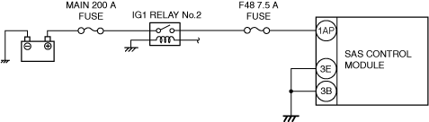
• IG1 relay No.2 malfunction
• DTCs are stored in the SAS control module.
• Battery malfunction
• Generator system malfunction
• SAS control module connector or terminal malfunction
• SAS control module malfunction
• Instrument cluster malfunction
• Malfunction in CAN line between the SAS control module and instrument cluster
• Open circuit in SAS control module power supply circuit
• Short to ground in SAS control module power supply circuit
• Open circuit in SAS control module ground circuit
|
|
 |
||
 |
||
-
Warning
-
• Handling the component parts improperly can accidentally operate (deploy) the air bag module, which may seriously injure you. Read the service warnings/cautions and the workshop manual before handling the air bag system components. (See AIR BAG SYSTEM SERVICE WARNINGS [STANDARD DEPLOYMENT CONTROL SYSTEM – MEXICO SPEC.].) (See AIR BAG SYSTEM SERVICE CAUTIONS [STANDARD DEPLOYMENT CONTROL SYSTEM – MEXICO SPEC.].) (See AIR BAG SYSTEM SERVICE WARNINGS [TWO-STEP DEPLOYMENT CONTROL SYSTEM – US/CANADA SPEC.].) (See AIR BAG SYSTEM SERVICE CAUTIONS [TWO-STEP DEPLOYMENT CONTROL SYSTEM – US/CANADA SPEC.].)
Diagnostic Procedure
|
Step |
Inspection |
Action |
|
|---|---|---|---|
|
1
|
INSPECT IG1 RELAY No.2
• Switch the ignition off.
• Disconnect the negative battery terminal. (See NEGATIVE BATTERY TERMINAL DISCONNECTION/CONNECTION [(US)].)
• Inspect the IG1 relay No.2. (See RELAY INSPECTION.)
• Is the IG1 relay No.2 normal?
|
Yes
|
Go to the next step.
|
|
No
|
Replace the IG1 relay No.2, then perform the repair completion verification.
(See RELAY LOCATION [(US)].)
|
||
|
2
|
INSPECT SAS CONTROL MODULE DTC
• Perform the SAS control module DTC inspection using the M-MDS. (See DTC INSPECTION.)
• Are any DTCs present?
|
Yes
|
Go to the applicable DTC inspection.
|
|
No
|
Go to the next step.
|
||
|
3
|
INSPECT BATTERY
• Inspect the battery. (See BATTERY INSPECTION [(US)].)
• Is the battery normal?
|
Yes
|
Go to the next step.
|
|
No
|
Replace or charge the battery.
(See BATTERY RECHARGING [(US)].)
Then perform the repair completion verification.
|
||
|
4
|
INSPECT GENERATOR
• Inspect the generator. (See GENERATOR INSPECTION [SKYACTIV-G (WITHOUT CYLINDER DEACTIVATION (US))].) (See GENERATOR INSPECTION [SKYACTIV-G (WITH CYLINDER DEACTIVATION (US))].)
• Is the generator normal?
|
Yes
|
Go to the next step.
|
|
No
|
Replace the generator, then go to perform the repair completion verification.
|
||
|
5
|
VERIFY THAT SAS CONTROL MODULE CONNECTOR IS CONNECTED
• Switch the ignition off.
• Disconnect the negative battery terminal and wait for 1 min or more. (See NEGATIVE BATTERY TERMINAL DISCONNECTION/CONNECTION [(US)].)
• Verify the condition of the SAS control module connectors. (See SAS CONTROL MODULE REMOVAL/INSTALLATION [STANDARD DEPLOYMENT CONTROL SYSTEM – MEXICO SPEC.].) (See SAS CONTROL MODULE REMOVAL/INSTALLATION [TWO-STEP DEPLOYMENT CONTROL SYSTEM – US/CANADA SPEC.].)
• Are all SAS control module connectors securely connected?
|
Yes
|
Go to the next step.
|
|
No
|
Reconnect the connector properly, then go to perform the repair completion verification.
|
||
|
6
|
VERIFY THAT INSTRUMENT CLUSTER CONNECTOR IS CONNECTED
• Remove the instrument cluster. (See INSTRUMENT CLUSTER REMOVAL/INSTALLATION.)
• Are all instrument cluster connectors securely connected?
|
Yes
|
Go to the next step.
|
|
No
|
Reconnect the connector properly, then go to perform the repair completion verification.
|
||
|
7
|
INSPECT DTCs IN SAS CONTROL MODULE
• Connect the negative battery terminal. (See NEGATIVE BATTERY TERMINAL DISCONNECTION/CONNECTION [(US)].)
• Switch the ignition ON (engine off or on).
• Clear the DTC for the SAS control module using the M-MDS. (See CLEARING DTC.)
• Inspect the DTC for the SAS control module on-board diagnostic system. (See DTC INSPECTION.)
• Have DTCs been recorded in memory?
|
Yes
|
Perform the applicable DTC inspection, then perform the repair completion verification.
|
|
No
|
Go to the next step.
|
||
|
8
|
INSPECT DTCs IN BCM
• Inspect the DTC for the BCM on-board diagnostic system. (See DTC INSPECTION.)
• Are the any DTCs present?
|
Yes
|
Perform the applicable DTC inspection, then perform the repair completion verification.
|
|
No
|
Go to the next step.
|
||
|
9
|
VERIFY SAS CONTROL MODULE CONNECTOR CONDITION
• Switch the ignition off.
• Disconnect the negative battery terminal and wait for 1 min or more. (See NEGATIVE BATTERY TERMINAL DISCONNECTION/CONNECTION [(US)].)
• Disconnect all SAS control module connectors. (See SAS CONTROL MODULE REMOVAL/INSTALLATION [STANDARD DEPLOYMENT CONTROL SYSTEM – MEXICO SPEC.].) (See SAS CONTROL MODULE REMOVAL/INSTALLATION [TWO-STEP DEPLOYMENT CONTROL SYSTEM – US/CANADA SPEC.].)
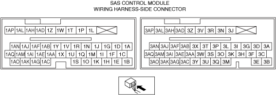
• Inspect the connector engagement and connection condition and inspect the terminals for damage, deformation, corrosion, or disconnection.
• Is the connector normal?
|
Yes
|
Go to the next step.
|
|
No
|
Replace the air bag harness, then perform the repair completion verification.
|
||
|
10
|
INSPECT SAS CONTROL MODULE POWER SUPPLY CIRCUIT FOR SHORT TO GROUND AND OPEN CIRCUIT
• Inspect the power supply circuit for an open circuit and short to ground. (See CIRCUIT INSPECTION.)
• Is the circuit normal?
|
Yes
|
Go to the next step.
|
|
No
|
Repair or replace the malfunctioning location and perform the repair completion verification.
|
||
|
11
|
INSPECT SAS CONTROL MODULE GROUND CIRCUIT FOR OPEN CIRCUIT
• Inspect the ground circuit for an open circuit. (See CIRCUIT INSPECTION.)
• Is the circuit normal?
|
Yes
|
Repair the instrument cluster, then perform the repair completion verification.
|
|
No
|
Repair or replace the malfunctioning location and perform the repair completion verification.
|
||
|
Repair completion verification
|
VERIFY THAT MALFUNCTION SYMPTOMS DO NOT RECUR AFTER REPAIR
• Connect the SAS control module connectors.
• Reconnect all disconnected connectors.
• Connect the negative battery terminal. (See NEGATIVE BATTERY TERMINAL DISCONNECTION/CONNECTION [(US)].)
• Switch the ignition ON (engine off or on).
• Does the air bag system warning light illuminate for approx. 6 s and turn off?
|
Yes
|
Verify that there are no DTCs in the memory. If there are no DTCs, the troubleshooting is completed.
|
|
No
|
Refer to the controller area network (CAN) malfunction diagnosis flow to inspect for a CAN communication error.
• If the CAN communication is normal, replace the SAS control module. (See SAS CONTROL MODULE REMOVAL/INSTALLATION [STANDARD DEPLOYMENT CONTROL SYSTEM – MEXICO SPEC.].) (See SAS CONTROL MODULE REMOVAL/INSTALLATION [TWO-STEP DEPLOYMENT CONTROL SYSTEM – US/CANADA SPEC.].)
|
||