FRONT STABILIZER REMOVAL [(US)]
FRONT STABILIZER REMOVAL [(US)]
SM2334999
id0213008034x1
-
Caution
-
• If the front ABS wheel-speed sensor wiring harness is pulled by mistake when performing this procedure, it could cause open circuit. Before servicing, disconnect the front ABS wheel-speed sensor and set it aside so that the wiring harness will not be pulled by mistake.• If the steering wheel rotates after the steering shaft and the steering gear and linkage are disconnected, the internal parts of the clock spring could be damaged. After disconnecting the steering shaft, secure the steering wheel using tape or cable to prevent it from rotating.• Do not allow the dust boot of the front stabilizer control link to touch the body, the front shock absorber and coil spring, and the hand tool. Otherwise, the dust boot of the front stabilizer control link could be damaged.
1.Remove the wheel and tire. (See WHEEL AND TIRE REMOVAL/INSTALLATION.)
2.Disconnect the rubber from the bracket.
am3zzw00023037
|
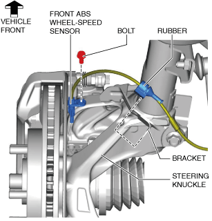
3.Disconnect the front ABS wheel-speed sensor wiring harness on the steering knuckle and set it aside so that it does not interfere with the servicing.
4.Remove the tunnel cover. (See EXHAUST SYSTEM REMOVAL/INSTALLATION [SKYACTIV-G (WITHOUT CYLINDER DEACTIVATION (US))].) (See EXHAUST SYSTEM REMOVAL/INSTALLATION [SKYACTIV-G (WITH CYLINDER DEACTIVATION (US))].)
5.Remove the following parts.
- (1)Front undercover No.1 (See FRONT UNDER COVER No.1 REMOVAL/INSTALLATION.)
- (2)Front undercover No.2 (See FRONT UNDER COVER No.2 REMOVAL/INSTALLATION.)
6. Disconnect the tie-rod end from the steering knuckle. (See TIE-ROD END REPLACEMENT.)
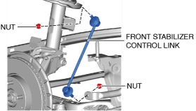
7.Remove the front stabilizer control link. (See Front Stabilizer Control Link Removal Note.)
am3zzw00023038
|
8.Disconnect the front lower arm ball joint from the steering knuckle. (See FRONT LOWER ARM REMOVAL/INSTALLATION [(US)].)
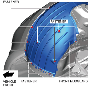
9.Remove the fastener shown in the figure and slightly bend back the front mudguard.
am3zzw00023039
|
10.Remove the front deflector. (See DEFLECTOR REMOVAL/INSTALLATION.)
11.Remove the front splash shield. (See SPLASH SHIELD REMOVAL/INSTALLATION.)
12.Remove the joint cover. (See STEERING WHEEL AND COLUMN REMOVAL/INSTALLATION [(US)].)
13.Disconnect the intermediate shaft from the steering gear and linkage. (See STEERING WHEEL AND COLUMN REMOVAL/INSTALLATION [(US)].)
14.Remove the front crossmember component. (See FRONT CROSSMEMBER REMOVAL/INSTALLATION [(US)].)
15.Remove the hole cover No.1 and hole cover No.2. (See FRONT CROSSMEMBER REMOVAL/INSTALLATION [(US)].)
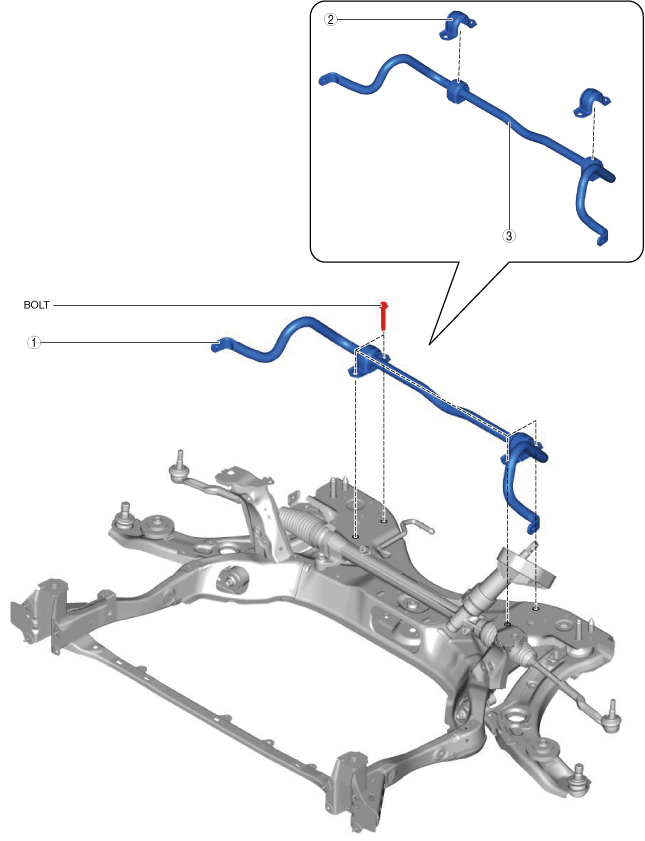
16.Remove in the order shown in the figure.
am3zzw00023040
|
|
1
|
Front stabilizer component
|
|
2
|
Front stabilizer bracket
|
|
3
|
Front stabilizer
|
Front Stabilizer Control Link Removal Note
-
Caution
-
• Use a hand tool when removing the nuts. Otherwise, the front stabilizer control link ball joint could be damaged.
1.Insert a hexagon wrench into the ball joint stud.
2.Remove the nuts so that the ball joint does not rotate.
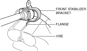
Front Stabilizer Bracket Removal Note
1.If the front stabilizer bracket cannot be removed by hand, remove it using a vise.
ac8wzw00001926
|
-
Caution
-
• The front stabilizer bracket may deform if it is removed using a vise. When removing the front stabilizer bracket using a vise, secure the front stabilizer bracket flange to the vise as shown in the figure, then remove it.