DTC P1450:00 [PCM (SKYACTIV-G)]
DTC P1450:00 [PCM (SKYACTIV-G)]
SM2334453
id0102t4303100
-
Note
-
• To determine the malfunctioning part, proceed with the diagnostics from “Function Inspection Using M-MDS”.
Details On DTCs
|
Description |
Evaporator system: abnormal negative pressure in fuel tank |
|
|---|---|---|
|
Detection condition
|
Determination conditions
|
• Target negative pressure exceeding the specified time or more is generated from negative pressure inducted to the fuel tank by the operation of the purge solenoid valve after the fuel tank is sealed (CV solenoid valve ON).
|
|
Preconditions
|
• Evaporative gas flow amount: Exceeds 10,000 cm3/min or fuel tank vacuum is high
• Fuel tank pressure: −4,340.2—4,030.1 Pa {−442.57—410.95 kgf/m2, −0.62949—0.58452 psi} *1
• IAT sensor No.1: 4.44—43.33 °C {40.0—109.9 °F} *1
• Vehicle speed: 64—145 km/h {40.0—90.0 mph} *1
• Barometric pressure: 72.23 kPa {0.7365 kgf/cm2, 10.48 psi} or more *1
• Period ignition is switched off before engine starts: 210 min or more
• Fuel level in fuel tank: 15—85 % *1
• Minimum value of intake manifold vacuum: 4 kPa {0.04 kgf/cm2, 0.6 psi} or more
• Minimum value of intake air amount: more than 2 g/sec
• Battery voltage: more than 11 V *1
• The following DTCs are not detected:
*1: Standard can be verified by displaying PIDs using M-MDS
|
|
|
Malfunction determination period
|
• 75 s period
|
|
|
Drive cycle
|
• 2
|
|
|
Self test type
|
• CMDTC self test
|
|
|
Sensor used
|
• Fuel tank pressure sensor
|
|
|
Fail-safe function
|
• Not applicable
|
|
|
Vehicle status when DTCs are output
|
• Not applicable
|
|
|
Possible cause
|
• Clogging between fuel tank and fuel tank pressure sensor
• Fuel tank pressure sensor malfunction
• Restriction between charcoal canister main and release-side passage
• Purge solenoid valve malfunction
• Pressure control valve malfunction
• PCM malfunction
|
|
System Wiring Diagram
• Not applicable
Function Explanation (DTC Detection Outline)
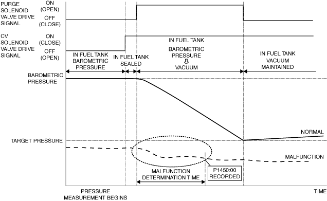
• The PCM closes the purge solenoid valve and CV solenoid valve while the vehicle is being driven and seals the fuel tank. Then, the evaporative gas in the fuel tank is inducted into the intake manifold and the pressure in the fuel tank is decreased by opening the purge solenoid valve, and the pressure change of the fuel tank is measured using the fuel tank pressure sensor. If the pressure in the fuel tank decreases below the target negative pressure for the specified period from the pressure measurement, the PCM determines that abnormal negative pressure in the fuel tank is being generated and stores a DTC.
am3zzw00033488
|
Repeatability Verification Procedure
1. Set the remaining fuel quantity in the fuel tank between 30—85 %.
2. Verify that OBD-II information (such as freeze frame data) has been obtained and recorded.
3. Clear the DTC from the PCM memory using the M-MDS. (See CLEARING DTC.)
4. Start the engine and switch the ignition off after 5 s have elapsed.
5. Leave the vehicle for 6 hours or more.
6. Start the engine and leave it idling for 2 min.
7. Drive the vehicle for 30 min at a speed of 50 km/h {31 mph} or more (to increase temperature in fuel tank and generate evaporative gas).
-
Note
-
• If driving the vehicle for 30 min at a speed of 50 km/h {31 mph} or more is not feasible, the vehicle can be driven for a continuous 15 min or more with the engine coolant temperature at 80 °C {176 °F} or more.
8. Stop the engine.
9. Leave the vehicle for 1 hours or more.
PID Item/Simulation Item Used In Diagnosis
PID/DATA monitor item table
|
PIDs |
Reference |
|---|---|
|
EVAP_PRES
|
|
|
FTP
|
Simulation item table
|
Simulation items |
Reference |
|---|---|
|
PRG_DUTY
|
|
|
CSTR_VENT_SOL_DUTY
|
Function Inspection Using M-MDS
|
Step |
Inspection |
Results |
Action |
|---|---|---|---|
|
1
|
PURPOSE: VERIFY RELATED REPAIR INFORMATION OR SERVICE INFORMATION AVAILABILITY
• Verify related Service Bulletins, on-line repair information, or Service Information availability.
• Is any related Information available?
|
Yes
|
Perform repair or diagnosis according to the available information.
• If the vehicle is not repaired, go to the next step.
|
|
No
|
Go to the next step.
|
||
|
2
|
PURPOSE: RECORD VEHICLE STATUS WHEN DTC WAS DETECTED TO UTILIZE WITH REPEATABILITY VERIFICATION
• Record the freeze frame data/snapshot data and diagnostic monitoring test results (EVAP system related).
|
—
|
Go to the next step.
|
|
3
|
PURPOSE: INSPECTION OF CLOGGING BETWEEN FUEL TANK PRESSURE SENSOR AND FUEL TANK
• Perform the DTC inspection for the PCM. (See DTC INSPECTION.)
• Are any of the following DTCs displayed?
|
Yes
|
The possibility of clogging between fuel tank pressure sensor and fuel tank is high.
• Repair the malfunctioning location according to the applicable DTC troubleshooting. (See DTC P144A:00 [PCM (SKYACTIV-G)].)
|
|
No
|
Go to the next step.
|
||
|
4
|
PURPOSE: VERIFY FUEL TANK PRESSURE SENSOR MEASURED CORRECTLY
• Start the engine and idle it.
• Access the following simulation items using the M-MDS: (See SIMULATION INSPECTION.)
• Change to the following conditions using the simulation function.
• Access the FTP PID using the M-MDS. (See PID/DATA MONITOR INSPECTION.)
• Does the negative pressure change when racing the engine?
|
Yes
|
Go to the next step.
|
|
No
|
Go to Troubleshooting Diagnostic Procedure to perform the procedure from Step 1.
|
||
|
5
|
PURPOSE: VERIFY IF ATMOSPHERE BETWEEN CV SOLENOID VALVE AND ATMOSPHERE CAN RELEASE
• Access the following simulation items using the M-MDS: (See SIMULATION INSPECTION.)
• Change to the following conditions using the simulation function.
• Access the EVAP_PRES PID using the M-MDS. (See PID/DATA MONITOR INSPECTION.)
• Is the displayed PID value as follows?
|
Yes
|
Go to the next step.
|
|
No
|
Go to Troubleshooting Diagnostic Procedure to perform the procedure from Step 2.
|
||
|
6
|
PURPOSE: VERIFY IF PURGE SOLENOID VALVE IS STUCK OPEN
• Access the following simulation items using the M-MDS: (See SIMULATION INSPECTION.)
• Change to the following conditions using the simulation function.
• Access the FTP PID using the M-MDS. (See PID/DATA MONITOR INSPECTION.)
• Is the FTP PID value negative pressure?
|
Yes
|
Go to Troubleshooting Diagnostic Procedure to perform the procedure from Step 6.
|
|
No
|
Go to Troubleshooting Diagnostic Procedure to perform the procedure from Step 1.
|
Troubleshooting Diagnostic Procedure
Intention of troubleshooting procedure
• Step 1
-
― Perform a PCM input signal part-related inspection.
• Step 2—5
-
― Verify if there is restriction in atmosphere release passage.
• Step 6
-
― Perform the inspection for a purge solenoid valve stuck open.
• Step 7
-
― Perform a unit inspection of the pressure control valve.
• Repair completion verification
-
― Verify that the primary malfunction is resolved and there are no other malfunctions.
|
Step |
Inspection |
Results |
Action |
|---|---|---|---|
|
1
|
PURPOSE: INSPECT FUEL TANK PRESSURE SENSOR FOR MALFUNCTION
• Inspect the applicable part. (See FUEL TANK PRESSURE SENSOR INSPECTION [SKYACTIV-G (WITH CYLINDER DEACTIVATION (US))].) (See FUEL TANK PRESSURE SENSOR INSPECTION [SKYACTIV-G (WITHOUT CYLINDER DEACTIVATION (US))].)
• Is the part normal?
|
Yes
|
Go to the next step.
|
|
No
|
Repair or replace the malfunctioning location and perform the repair completion verification.
|
||
|
2
|
PURPOSE: INSPECT CV SOLENOID VALVE FOR MALFUNCTION
• Inspect the applicable part. (See CANISTER VENT (CV) SOLENOID VALVE INSPECTION [SKYACTIV-G (WITH CYLINDER DEACTIVATION (US))].) (See CANISTER VENT (CV) SOLENOID VALVE INSPECTION [SKYACTIV-G (WITHOUT CYLINDER DEACTIVATION (US))].)
• Is the part normal?
|
Yes
|
Go to the next step.
|
|
No
|
Repair or replace the malfunctioning location and perform the repair completion verification.
|
||
|
3
|
PURPOSE: VERIFY IF THERE IS RESTRICTION BETWEEN CHARCOAL CANISTER AND ATMOSPHERE RELEASE PASSAGE
• Verify the following passage hoses, pipe connection condition, and that there is no restriction.
• Is there any poor connection or restriction?
|
Yes
|
Repair or replace the malfunctioning location and perform the repair completion verification.
|
|
No
|
Go to the next step.
|
||
|
4
|
PURPOSE: INSPECT CHARCOAL CANISTER MAIN FOR MALFUNCTION
• Inspect the applicable part. (See CHARCOAL CANISTER INSPECTION [SKYACTIV-G (WITH CYLINDER DEACTIVATION (US))].) (See CHARCOAL CANISTER INSPECTION [SKYACTIV-G (WITHOUT CYLINDER DEACTIVATION (US))].)
• Is the part normal?
|
Yes
|
Go to the next step.
|
|
No
|
Repair or replace the malfunctioning location and perform the repair completion verification.
|
||
|
5
|
PURPOSE: INSPECT CHARCOAL CANISTER SUB FOR MALFUNCTION
• Inspect the applicable part. (See CHARCOAL CANISTER INSPECTION [SKYACTIV-G (WITH CYLINDER DEACTIVATION (US))].) (See CHARCOAL CANISTER INSPECTION [SKYACTIV-G (WITHOUT CYLINDER DEACTIVATION (US))].)
• Is the part normal?
|
Yes
|
Go to the next step.
|
|
No
|
Repair or replace the malfunctioning location and perform the repair completion verification.
|
||
|
6
|
PURPOSE: INSPECT PURGE SOLENOID VALVE FOR MALFUNCTION
• Inspect the applicable part. (See PURGE SOLENOID VALVE INSPECTION [SKYACTIV-G (WITH CYLINDER DEACTIVATION (US))].) (See PURGE SOLENOID VALVE INSPECTION [SKYACTIV-G (WITHOUT CYLINDER DEACTIVATION (US))].)
• Is the part normal?
|
Yes
|
Go to the next step.
|
|
No
|
Repair or replace the malfunctioning location and perform the repair completion verification.
|
||
|
7
|
PURPOSE: INSPECT PRESSURE CONTROL VALVE FOR MALFUNCTION
• Inspect the applicable part. (See PRESSURE CONTROL VALVE INSPECTION [SKYACTIV-G (WITH CYLINDER DEACTIVATION (US))].) (See PRESSURE CONTROL VALVE INSPECTION [SKYACTIV-G (WITHOUT CYLINDER DEACTIVATION (US))].)
• Is the part normal?
|
Yes
|
Go to the next step.
|
|
No
|
Repair or replace the malfunctioning location and perform the repair completion verification.
|
||
|
Repair completion verification 1
|
PURPOSE: VERIFY THAT VEHICLE IS REPAIRED
• Install/connect the part removed/disconnected during the troubleshooting procedure.
• Clear the DTC recorded in the memory. (See CLEARING DTC.)
• Replicate the vehicle conditions at the time the DTC was detected using the following procedure.
• Perform the DTC inspection for the PCM. (See DTC INSPECTION.)
• Is the same Pending DTC present?
|
Yes
|
Refer to the controller area network (CAN) malfunction diagnosis flow to inspect for a CAN communication error.
If the CAN communication is normal, perform the diagnosis from Step 1.
• If the malfunction recurs, replace the PCM, then go to the next step. (See PCM REMOVAL/INSTALLATION [SKYACTIV-G (WITH CYLINDER DEACTIVATION (US))].) (See PCM REMOVAL/INSTALLATION [SKYACTIV-G (WITHOUT CYLINDER DEACTIVATION (US))].)
|
|
No
|
Go to the next step.
|
||
|
Repair completion verification 2
|
PURPOSE: VERIFY IF OTHER DTCs DISPLAYED
• Perform the DTC inspection. (See DTC INSPECTION.)
• Are any other DTCs displayed?
|
Yes
|
Repair the malfunctioning location according to the applicable DTC troubleshooting.
|
|
No
|
DTC troubleshooting completed.
|