DTC P055F:00 [PCM (SKYACTIV-G)]
DTC P055F:00 [PCM (SKYACTIV-G)]
SM2334430
id0102t4215300
-
Note
-
• To determine the malfunctioning part, proceed with the diagnostics from “Function Inspection Using M-MDS”.
Details On DTCs
|
Description |
Engine oil pressure malfunction |
||
|---|---|---|---|
|
Detection condition
|
Determination conditions
|
• If any of the following conditions is met under condition A or condition B:
|
|
|
Drive cycle
|
• 2
|
||
|
Self test type
|
• CMDTC self test
|
||
|
Sensor used
|
• Engine oil pressure sensor
|
||
|
Fail-safe function
|
Condition A:
• Not applicable.
Condition B:
• Restricts the upper limit of the engine speed.
• PCM restricts engine torque.
|
||
|
Vehicle status when DTCs are output
|
• The engine could be damaged due to an engine hydraulic pressure malfunction.
|
||
|
Possible cause
|
• Engine oil leakage
• Improper engine oil level
• Oil strainer clogging
• Engine oil temperature sensor/engine oil pressure sensor connector or terminals malfunction
• PCM connector or terminals malfunction
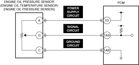
• Short to ground in any of the following engine oil pressure sensor circuits.
• Open circuit in any of the following engine oil pressure sensor circuits.
• Short to power supply in any of the following engine oil pressure sensor circuits.
• Short circuit between any of the following engine oil pressure sensor circuits.
• Engine oil pressure sensor malfunction
• Engine oil solenoid valve malfunction
• Oil pump malfunction
• PCM malfunction
|
||
 |
|||
 |
|||
 |
|||
Function Explanation (DTC Detection Outline)
• If low oil pressure continues, engine oil cannot be sent to each oil gallery which could damage the engine. If high oil pressure continues, excess engine oil is dispersed from the oil jet valve into the cylinder which could cause poor environmental performance and fuel economy.
• The PCM determines that the engine oil pressure is abnormal and stores a DTC if the actual oil pressure value does not get closer to the target oil pressure value.
Repeatability Verification Procedure
1. Start the engine.
Diagnostic Procedure
|
Step |
Inspection |
Results |
Action |
|---|---|---|---|
|
1
|
RECORD VEHICLE STATUS WHEN DTC WAS DETECTED TO UTILIZE WITH REPEATABILITY VERIFICATION
• Record the freeze frame data/snapshot data.
|
—
|
Go to the next step.
|
|
2
|
VERIFY RELATED REPAIR INFORMATION OR SERVICE INFORMATION AVAILABILITY
• Verify related Service Bulletins, on-line repair information, or Service Information availability.
• Is any related Information available?
|
Yes
|
Perform repair or diagnosis according to the available information.
• If the vehicle is not repaired, go to the next step.
|
|
No
|
Go to the next step.
|
||
|
3
|
INSPECT ENGINE OIL LEAKAGE
• Start the engine.
• Verify that there is no engine oil leakage in the hydraulic circuit.
• Is there any leakage?
|
Yes
|
Repair or replace the malfunctioning location, then add genuine motor oil.
Go to repair completion verification.
|
|
No
|
Go to the next step.
|
||
|
4
|
INSPECT ENGINE OIL LEVEL
• Inspect the engine oil level. (See ENGINE OIL LEVEL INSPECTION [SKYACTIV-G (WITH CYLINDER DEACTIVATION (US))].) (See ENGINE OIL LEVEL INSPECTION [SKYACTIV-G (WITHOUT CYLINDER DEACTIVATION (US))].)
• Is the engine oil level sufficient?
|
Yes
|
Go to the next step.
|
|
No
|
Add genuine motor oil and perform the repair completion verification.
|
||
|
5
|
INSPECT OIL STRAINER
• Inspect the oil strainer for clogging. (See OIL PUMP REMOVAL/INSTALLATION [SKYACTIV-G (WITH CYLINDER DEACTIVATION (US))].) (See OIL PUMP REMOVAL/INSTALLATION [SKYACTIV-G (WITHOUT CYLINDER DEACTIVATION (US))].)
• Is there any malfunction?
|
Yes
|
Replace the oil strainer and perform the repair completion verification.
|
|
No
|
Go to the next step.
|
||
|
6
|
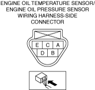
INSPECT ENGINE OIL TEMPERATURE SENSOR/ENGINE OIL PRESSURE SENSOR CONNECTOR FOR MALFUNCTION
• Inspect the applicable connector and terminal. (See CONNECTOR INSPECTION.)
• Are the connector and terminal normal?
|
Yes
|
Go to the next step.
|
|
No
|
Repair or replace the malfunctioning location and perform the repair completion verification.
|
||
|
7
|
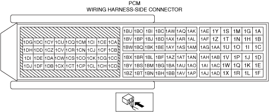
INSPECT PCM CONNECTOR FOR MALFUNCTION
• Inspect the applicable connector and terminal. (See CONNECTOR INSPECTION.)
• Are the connector and terminal normal?
|
Yes
|
Go to the next step.
|
|
No
|
Repair or replace the malfunctioning location and perform the repair completion verification.
|
||
|
8
|
INSPECT ENGINE OIL PRESSURE SENSOR POWER SUPPLY CIRCUITS, SIGNAL CIRCUITS, AND GROUND CIRCUITS FOR SHORT TO GROUND
• Inspect the applicable circuit for a short to ground. (See CIRCUIT INSPECTION.)
• Is the circuit normal?
|
Yes
|
Go to the next step.
|
|
No
|
Repair or replace the malfunctioning location and perform the repair completion verification.
|
||
|
9
|
INSPECT ENGINE OIL PRESSURE SENSOR POWER SUPPLY CIRCUITS, SIGNAL CIRCUITS, AND GROUND CIRCUITS FOR OPEN CIRCUIT
• Inspect the applicable circuit for open circuit. (See CIRCUIT INSPECTION.)
• Is the circuit normal?
|
Yes
|
Go to the next step.
|
|
No
|
Repair or replace the malfunctioning location and perform the repair completion verification.
|
||
|
10
|
INSPECT ENGINE OIL PRESSURE SENSOR POWER SUPPLY CIRCUITS, SIGNAL CIRCUITS, AND GROUND CIRCUITS FOR SHORT TO POWER SUPPLY
• Inspect the applicable circuit for a short to power supply. (See CIRCUIT INSPECTION.)
• Is the circuit normal?
|
Yes
|
Go to the next step.
|
|
No
|
Repair or replace the malfunctioning location and perform the repair completion verification.
|
||
|
11
|
INSPECT ENGINE OIL PRESSURE SENSOR POWER SUPPLY CIRCUITS, SIGNAL CIRCUITS, AND GROUND CIRCUITS FOR SHORT CIRCUIT
• Inspect the applicable circuits for a short circuit. (See CIRCUIT INSPECTION.)
• Is the circuit normal?
|
Yes
|
Go to the next step.
|
|
No
|
Repair or replace the malfunctioning location and perform the repair completion verification.
|
||
|
12
|
INSPECT ENGINE OIL PRESSURE SENSOR FOR MALFUNCTION
• Inspect the applicable part. (See ENGINE OIL PRESSURE SENSOR INSPECTION [SKYACTIV-G (WITH CYLINDER DEACTIVATION (US))].) (See ENGINE OIL PRESSURE SENSOR INSPECTION [SKYACTIV-G (WITHOUT CYLINDER DEACTIVATION (US))].)
• Is the part normal?
|
Yes
|
Go to the next step.
|
|
No
|
Repair or replace the malfunctioning location and perform the repair completion verification.
|
||
|
13
|
INSPECT ENGINE OIL SOLENOID VALVE FOR MALFUNCTION
• Inspect the applicable part. (See ENGINE OIL SOLENOID VALVE INSPECTION [SKYACTIV-G (WITH CYLINDER DEACTIVATION (US))].) (See ENGINE OIL SOLENOID VALVE INSPECTION [SKYACTIV-G (WITHOUT CYLINDER DEACTIVATION (US))].)
• Is the part normal?
|
Yes
|
Replace the oil pump and perform the repair completion verification.
|
|
No
|
Repair or replace the malfunctioning location and perform the repair completion verification.
|
||
|
Repair completion verification 1
|
VERIFY THAT VEHICLE IS REPAIRED
• Install/connect the part removed/disconnected during the troubleshooting procedure.
• Clear the DTC recorded in the memory. (See CLEARING DTC.)
• Replicate the vehicle conditions at the time the DTC was detected using the following procedure.
• Perform the DTC inspection for the PCM. (See DTC INSPECTION.)
• Is the same Pending DTC present?
|
Yes
|
Refer to the controller area network (CAN) malfunction diagnosis flow to inspect for a CAN communication error.
If the CAN communication is normal, perform the diagnosis from Step 1.
• If the malfunction recurs, replace the PCM, then go to the next step. (See PCM REMOVAL/INSTALLATION [SKYACTIV-G (WITH CYLINDER DEACTIVATION (US))].) (See PCM REMOVAL/INSTALLATION [SKYACTIV-G (WITHOUT CYLINDER DEACTIVATION (US))].)
|
|
No
|
Go to the next step.
|
||
|
Repair completion verification 2
|
VERIFY IF OTHER DTCs DISPLAYED
• Perform the DTC inspection. (See DTC INSPECTION.)
• Are any other DTCs displayed?
|
Yes
|
Repair the malfunctioning location according to the applicable DTC troubleshooting.
|
|
No
|
DTC troubleshooting completed.
|