ADVANCED KEYLESS ENTRY SYSTEM DOES NOT OPERATE [SECURITY AND LOCKS (US)]
ADVANCED KEYLESS ENTRY SYSTEM DOES NOT OPERATE [SECURITY AND LOCKS (US)]
SM2566395
id0903k70231ka
Outline
|
Description
|
• Cannot unlock even if door release touch sensor is touched.
• Cannot lock even if door lock touch sensor is touched.
|
|
|
Possible cause
|
• Remote transmitter malfunction
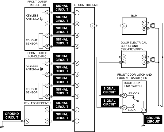
• Connector or terminal malfunction of the following parts:
• Short to ground or open circuit in keyless antenna (front outer handle) signal circuit
• Short to ground or open circuit in touch sensor (front outer handle) signal circuit
• Short to ground or open circuit in keyless receiver signal circuit
• Open circuit in keyless receiver ground circuit
• Short to ground or open circuit in door lock-link switch (front door latch and lock actuator) signal circuit
• Open circuit in door lock-link switch (front door latch and lock actuator) ground circuit
• Front outer handle malfunction
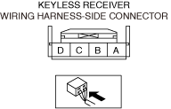
• Keyless receiver malfunction
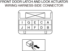
• Front door latch and lock actuator (driver’s side) malfunction
• LF control unit malfunction
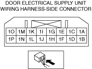
• Door-electrical supply unit (driver’s side) malfunction
• Non-designated battery is being used
|
|
 |
||
 |
 |
|
 |
 |
|
 |
 |
|
Diagnostic Procedure
|
Step |
Inspection |
Results |
Action |
|---|---|---|---|
|
1
|
VERIFY ALL SYSTEM DTCs
• Perform the DTC inspection. (See DTC INSPECTION.)
• Are any DTCs displayed?
|
Yes
|
Repair the malfunctioning location according to the applicable DTC troubleshooting.
|
|
No
|
Go to the next step.
|
||
|
2
|
INSPECT REMOTE TRANSMITTER FOR MALFUNCTION
• Verify if the remote transmitter is in power-saving mode.
• Is it in power-saving mode?
|
Yes
|
Go to the next step.
|
|
No
|
Repair or replace the malfunctioning location and perform the repair completion verification.
|
||
|
3
|
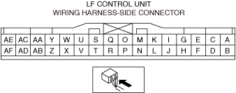
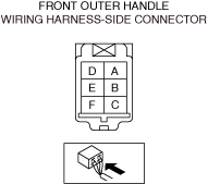
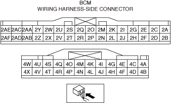
INSPECT FRONT OUTER HANDLE, KEYLESS RECEIVER, LF CONTROL UNIT, BCM, DOOR-ELECTRICAL SUPPLY UNIT (DRIVER’S SIDE), AND FRONT DOOR LATCH AND LOCK ACTUATOR (DRIVER’S SIDE) CONNECTORS FOR MALFUNCTION
• Inspect the applicable connector and terminal. (See CONNECTOR INSPECTION.)
• Are the connector and terminal normal?
|
Yes
|
Go to the next step.
|
|
No
|
Repair or replace the malfunctioning location and perform the repair completion verification.
|
||
|
4
|
INSPECT FRONT OUTER HANDLE POWER SUPPLY CIRCUIT FOR SHORT TO GROUND AND OPEN CIRCUIT
• Inspect the power supply circuit for a short to ground and open circuit. (See CIRCUIT INSPECTION.)
• Is the circuit normal?
|
Yes
|
Go to the next step.
|
|
No
|
Repair or replace the malfunctioning location and perform the repair completion verification.
|
||
|
5
|
INSPECT KEYLESS RECEIVER SIGNAL CIRCUIT FOR SHORT TO GROUND AND OPEN CIRCUIT
• Inspect the signal circuit for a short to ground and open circuit. (See CIRCUIT INSPECTION.)
• Is the circuit normal?
|
Yes
|
Go to the next step.
|
|
No
|
Repair or replace the malfunctioning location and perform the repair completion verification.
|
||
|
6
|
INSPECT KEYLESS RECEIVER GROUND CIRCUIT FOR OPEN CIRCUIT
• Inspect the ground circuit for open circuit. (See CIRCUIT INSPECTION.)
• Is the circuit normal?
|
Yes
|
Go to the next step.
|
|
No
|
Repair or replace the malfunctioning location and perform the repair completion verification.
|
||
|
7
|
INSPECT FRONT OUTER HANDLE FOR MALFUNCTION
• Inspect the applicable part. (See TOUCH SENSOR INSPECTION.)
• Is the part normal?
|
Yes
|
Go to the next step.
|
|
No
|
Repair or replace the malfunctioning location and perform the repair completion verification.
|
||
|
8
|
INSPECT KEYLESS RECEIVER FOR MALFUNCTION
• Inspect the applicable part. (See KEYLESS RECEIVER INSPECTION.)
• Is the part normal?
|
Yes
|
Go to the next step.
|
|
No
|
Repair or replace the malfunctioning location and perform the repair completion verification.
|
||
|
9
|
INSPECT FRONT DOOR LATCH AND LOCK ACTUATOR (DRIVER’S SIDE) FOR MALFUNCTION
• Inspect the applicable part. (See FRONT DOOR LATCH AND LOCK ACTUATOR INSPECTION [(US)].)
• Is the part normal?
|
Yes
|
Go to the next step.
|
|
No
|
Repair or replace the malfunctioning location and perform the repair completion verification.
|
||
|
10
|
INSPECT LF CONTROL UNIT FOR MALFUNCTION
• Inspect the applicable part. (See LF CONTROL UNIT INSPECTION [(US)].)
• Is the part normal?
|
Yes
|
Go to the next step.
|
|
No
|
Repair or replace the malfunctioning location and perform the repair completion verification.
|
||
|
Repair completion verification
|
VERIFY THAT VEHICLE IS REPAIRED
• Install/connect the part removed/disconnected during the troubleshooting procedure.
• Has the malfunction symptom been eliminated?
|
Yes
|
Complete the symptom troubleshooting. (Explain contents of repair to customer)
|
|
No
|
Refer to the controller area network (CAN) malfunction diagnosis flow to inspect for a CAN communication error.
If the CAN communication is normal, perform the diagnosis from Step 1.
• If the malfunction is not resolved, replace the door-electrical supply unit. (See DOOR-ELECTRICAL SUPPLY UNIT REMOVAL/INSTALLATION.)
|