ELECTRIC PARKING BRAKE AUTOMATIC RELEASE FUNCTION DURING ACCELERATION OPERATION TOO EARLY/LATE ON SLOPE [ELECTRIC PARKING BRAKE (US)]
ELECTRIC PARKING BRAKE AUTOMATIC RELEASE FUNCTION DURING ACCELERATION OPERATION TOO EARLY/LATE ON SLOPE [ELECTRIC PARKING BRAKE (US)]
SM2565951
id040328250734
|
Troubleshooting item |
Electric parking brake automatic release function during acceleration operation too early/late on slope |
|
|---|---|---|
|
Description
|
• Electric parking brake is released too early when the electric parking brake automatic release function during acceleration is operated on a slope.
• Electric parking brake is released too late when the electric parking brake automatic release function during acceleration is operated on a slope.
|
|
|
Possible cause
|
• DSC HU/CM malfunction
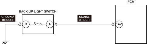
• Back-up light switch connector or terminal malfunction
• Back-up light switch malfunction
• Open circuit in back-up light switch ground circuit
• PCM connector or terminal malfunction
• Short to ground in back-up light switch signal circuit
• Short to power supply in back-up light switch signal circuit
• PCM malfunction
• Open circuit in back-up light switch signal circuit
|
|
 |
||
 |
||
 |
||
Diagnostic Procedure
|
Step |
Inspection |
Results |
Action |
|---|---|---|---|
|
1
|
VERIFY ALL SYSTEM DTCs
• Switch the ignition off.
• Switch the ignition ON (engine off or on) and wait for 10 s or more.
• Perform a DTC inspection using the M-MDS. (See DTC INSPECTION.)
• Are any DTCs displayed?
|
Yes
|
Repair or replace the malfunctioning part according to the applicable DTC troubleshooting.
(See DTC TABLE [DSC HU/CM (US)].)
|
|
No
|
Go to the next step.
|
||
|
2
|
VERIFY IF THE ELECTRIC PARKING BRAKE WARNING LIGHT IS TURNED ON
• Verify if the electric parking brake warning light is turned on.
• Is the electric parking brake warning light turned on?
|
Yes
|
Perform an inspection referring to “ELECTRIC PARKING BRAKE WARNING LIGHT TURNS ON”.
|
|
No
|
ATX:
• Replace the DSC HU/CM, and perform the repair completion verification. (See DSC HU/CM REMOVAL/INSTALLATION [L.H.D. (US)].)
MTX:
• Go to the next step.
|
||
|
3
|
VERIFY IF BACK-UP LIGHTS ARE ILLUMINATED
• Shift the shift lever to the reverse position.
• Are the back-up lights illuminated?
|
Yes
|
Replace the DSC HU/CM, and perform the repair completion verification.
|
|
No
|
Go to the next step.
|
||
|
4
|
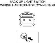
INSPECT BACK-UP LIGHT SWITCH CONNECTOR CONDITION
• Switch the ignition off.
• Disconnect the negative battery terminal. (See NEGATIVE BATTERY TERMINAL DISCONNECTION/CONNECTION [(US)].)
• Disconnect the back-up light switch connector.
• Inspect the connector engagement and connection condition and inspect the terminals for damage, deformation, corrosion, or disconnection.
• Is the connector normal?
|
Yes
|
Go to the next step.
|
|
No
|
Repair or replace the connector, and perform the repair completion verification.
|
||
|
5
|
INSPECT BACK-UP LIGHT SWITCH
• Inspect the back-up light switch. (See BACK-UP LIGHT SWITCH INSPECTION.)
• Is the back-up light switch normal?
|
Yes
|
Go to the next step.
|
|
No
|
Replace the back-up light switch, and perform the repair completion verification.
|
||
|
6
|
INSPECT BACK-UP LIGHT SWITCH GROUND CIRCUIT FOR OPEN CIRCUIT
• Inspect the ground circuit for an open circuit. (See CIRCUIT INSPECTION.)
• Is the circuit normal?
|
Yes
|
Go to the next step.
|
|
No
|
Repair or replace the malfunctioning location, and perform the repair completion verification.
|
||
|
7
|
INSPECT PCM CONNECTOR CONDITION
• Disconnect the PCM connector.
• Inspect the connector engagement and connection condition and inspect the terminals for damage, deformation, corrosion, or disconnection.
• Is the connector normal?
|
Yes
|
Go to the next step.
|
|
No
|
Repair or replace the connector, and perform the repair completion verification.
|
||
|
8
|
INSPECT BACK-UP LIGHT SWITCH SIGNAL CIRCUIT FOR SHORT TO GROUND
• Inspect the signal circuit for a short to ground. (See CIRCUIT INSPECTION.)
• Is the circuit normal?
|
Yes
|
Go to the next step.
|
|
No
|
Repair or replace the malfunctioning location, and perform the repair completion verification.
|
||
|
9
|
INSPECT BACK-UP LIGHT SWITCH SIGNAL CIRCUIT FOR SHORT TO POWER SUPPLY
• Inspect the signal circuit for a short to power supply. (See CIRCUIT INSPECTION.)
• Is the circuit normal?
|
Yes
|
Go to the next step.
|
|
No
|
Repair or replace the malfunctioning location, and perform the repair completion verification.
|
||
|
10
|
INSPECT BACK-UP LIGHT SWITCH SIGNAL CIRCUIT FOR OPEN CIRCUIT
• Inspect the signal circuit for an open circuit. (See CIRCUIT INSPECTION.)
• Is the circuit normal?
|
Yes
|
Replace the PCM, and perform the repair completion verification.
|
|
No
|
Repair or replace the malfunctioning location, and perform the repair completion verification.
|
||
|
Repair completion verification
|
VERIFY THAT MALFUNCTION SYMPTOMS DO NOT RECUR AFTER REPAIR
• Install/connect the part removed/disconnected during the troubleshooting procedure.
• Has the malfunction symptom been eliminated?
|
Yes
|
Complete the symptom troubleshooting.
Explain to the customer what has been repaired.
|
|
No
|
Refer to the controller area network (CAN) malfunction diagnosis flow to inspect for a CAN communication error.
If the CAN communication is normal, perform the diagnosis from Step 1.
|