DTC P0421:00 [PCM (SKYACTIV-G (US))]
DTC P0421:00 [PCM (SKYACTIV-G (US))]
SM2565565
id0102t47044u0
-
Note
-
• To determine the malfunctioning part, proceed with the diagnostics from “Function Inspection Using M-MDS”.
Details On DTCs
|
Description |
Catalytic converter system |
|
|---|---|---|
|
Detection condition
|
Determination conditions
|
• The PCM detects that the HO2S output fluctuates from lean to rich in a short amount of time at specified times continuously after recovery from fuel cut control.
|
|
Preconditions
|
• Catalytic converter (WU-TWC) is activated sufficiently.
• A/F sensor is activated sufficiently.
• HO2S is activated sufficiently.
• The following DTCs are not detected:
|
|
|
Drive cycle
|
• 1 (U.S.A.)
• 2 (except U.S.A.)
|
|
|
Self test type
|
• CMDTC self test
|
|
|
Sensor used
|
• A/F sensor, HO2S
|
|
|
Fail-safe function
|
• Not applicable
|
|
|
Vehicle status when DTCs are output
|
• Not applicable
|
|
|
Possible cause
|
• HO2S malfunction
• A/F sensor malfunction
• WU-TWC deterioration or malfunction
• PCM malfunction
|
|
System Wiring Diagram
• Not applicable
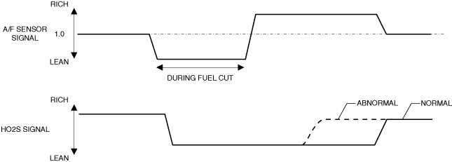
Function Explanation (DTC Detection Outline)
• The PCM monitors the oxygen storage amount proportional to the catalytic converter purification characteristic.
• The PCM starts to monitor after recovery (fuel injection starts) from fuel cut control during deceleration.
• The PCM temporarily changes the target air/fuel ratio to rich at recovery from fuel cut control, and detects the response time until the HO2S output signal outputs the voltage on the rich side.
• If the catalytic converter purification characteristic deteriorates, the amount of time until the HO2S detects the voltage on the rich side is shorter compared to the normal purification characteristic as shown in the figure.
• The PCM detects a catalytic converter malfunction using this characteristic.
am3zzw00033734
|
Repeatability Verification Procedure
1. Start the engine and leave it idling for 1 min.
2. Drive the vehicle normally for 15 min. After that, shift to 3rd gear and maintain the vehicle speed at approx. 40 km/h {25 mph}.
3. Accelerate the vehicle to 60 km/h {37 mph} while in 3rd gear.
4. Release the accelerator pedal and decelerate the vehicle to 40 km/h {25 mph}.
5. Accelerate the vehicle to 60 km/h {37 mph} again while in 3rd gear.
6. Drive the vehicle for 20 s at a speed of 50 km/h {31 mph} while in 3rd gear.
7. Repeat Step 4 to 6 operations above 20 times.
-
Note
-
• Match the engine coolant temperature in the recorded freeze frame data/snapshot data, the vehicle speed, and engine speed values to the best extent possible while driving the vehicle.
8. Try to reproduce the malfunction by driving the vehicle for 5 min based on the values in the freeze frame data/snapshot data.
PID Item/Simulation Item Used In Diagnosis
PID/DATA monitor item table
|
PIDs |
Reference |
|---|---|
|
A/F_SEN_CUR
|
|
|
HO2S_OUT_VOLT
|
Function Inspection Using M-MDS
|
Step |
Inspection |
Results |
Action |
|---|---|---|---|
|
1
|
PURPOSE: VERIFY RELATED REPAIR INFORMATION OR SERVICE INFORMATION AVAILABILITY
• Verify related Service Bulletins, on-line repair information, or Service Information availability.
• Is any related Information available?
|
Yes
|
Perform repair or diagnosis according to the available information.
• If the vehicle is not repaired, go to the next step.
|
|
No
|
Go to the next step.
|
||
|
2
|
PURPOSE: IDENTIFY TRIGGER DTC FOR FREEZE FRAME DATA
• Is the DTC P0421:00 on freeze frame data?
|
Yes
|
Go to the next step.
|
|
No
|
Go to the troubleshooting procedure for DTC on freeze frame data.
|
||
|
3
|
PURPOSE: RECORD VEHICLE STATUS WHEN DTC WAS DETECTED TO UTILIZE WITH REPEATABILITY VERIFICATION
• Record the freeze frame data/snapshot data and diagnostic monitoring test results (catalyst related).
|
—
|
Go to the next step.
|
|
4
|
PURPOSE: INSPECT FOR OTHER RELATED DTCs
• Perform the DTC inspection for the PCM. (See DTC INSPECTION.)
• Are any other DTCs displayed?
|
Yes
|
Repair the malfunctioning location according to the applicable DTC troubleshooting.
Go to the next step.
|
|
No
|
Go to the next step.
|
||
|
5
|
PURPOSE: VERIFY A/F SENSOR AND HO2S INPUT SIGNAL
• Start the engine and warm it up completely.
• Access the following PIDs using the M-MDS: (See PID/DATA MONITOR INSPECTION.)
• Drive the vehicle under the following conditions.
• Is the displayed PID value as follows?
|
Yes
|
Go to Troubleshooting Diagnostic Procedure to perform the procedure from Step 3.
|
|
No
|
Go to the next step.
|
||
|
6
|
PURPOSE: VERIFY CONNECTOR CONNECTIONS
• Access the following PIDs using the M-MDS: (See PID/DATA MONITOR INSPECTION.)
• Does the PID value fluctuate when the following connectors are shaken?
|
Yes
|
Repair or replace the applicable wiring harness or connector parts.
Go to Troubleshooting Diagnostic Procedure to perform the repair completion verification.
|
|
No
|
Go to Troubleshooting Diagnostic Procedure to perform the procedure from Step 1.
|
Troubleshooting Diagnostic Procedure
Intention of troubleshooting procedure
• Step 1—2
-
― Perform inspection of HO2S and A/F sensor signal related parts.
• Step 3—7
-
― Perform inspection of each separate part.
• Repair completion verification
-
― Verify that the primary malfunction is resolved and there are no other malfunctions.
|
Step |
Inspection |
Results |
Action |
|---|---|---|---|
|
1
|
PURPOSE: VERIFY IF HO2S IS INSTALLED CORRECTLY
• Verify the HO2S installation condition. (See HEATED OXYGEN SENSOR (HO2S) REMOVAL/INSTALLATION [SKYACTIV-G (WITH CYLINDER DEACTIVATION (US))].) (See HEATED OXYGEN SENSOR (HO2S) REMOVAL/INSTALLATION [SKYACTIV-G (WITHOUT CYLINDER DEACTIVATION (US))].)
• Is the installation condition normal?
|
Yes
|
Go to the next step.
|
|
No
|
Correctly install the HO2S and perform the repair completion verification.
|
||
|
2
|
PURPOSE: VERIFY IF A/F SENSOR IS INSTALLED CORRECTLY
• Verify the A/F sensor installation condition. (See AIR FUEL RATIO (A/F) SENSOR REMOVAL/INSTALLATION [SKYACTIV-G (WITH CYLINDER DEACTIVATION (US))].) (See AIR FUEL RATIO (A/F) SENSOR REMOVAL/INSTALLATION [SKYACTIV-G (WITHOUT CYLINDER DEACTIVATION (US))].)
• Is the installation condition normal?
|
Yes
|
Replace the A/F sensor and/or HO2S and perform the repair completion verification.
(See AIR FUEL RATIO (A/F) SENSOR REMOVAL/INSTALLATION [SKYACTIV-G (WITH CYLINDER DEACTIVATION (US))].)
(See AIR FUEL RATIO (A/F) SENSOR REMOVAL/INSTALLATION [SKYACTIV-G (WITHOUT CYLINDER DEACTIVATION (US))].)
|
|
No
|
Correctly install the A/F sensor and perform the repair completion verification.
|
||
|
3
|
PURPOSE: VERIFY IF HO2S IS INSTALLED CORRECTLY
• Verify the HO2S installation condition. (See HEATED OXYGEN SENSOR (HO2S) REMOVAL/INSTALLATION [SKYACTIV-G (WITH CYLINDER DEACTIVATION (US))].) (See HEATED OXYGEN SENSOR (HO2S) REMOVAL/INSTALLATION [SKYACTIV-G (WITHOUT CYLINDER DEACTIVATION (US))].)
• Is the installation condition normal?
|
Yes
|
Go to the next step.
|
|
No
|
Correctly install the HO2S and perform the repair completion verification.
|
||
|
4
|
PURPOSE: VERIFY IF A/F SENSOR IS INSTALLED CORRECTLY
• Verify the A/F sensor installation condition. (See AIR FUEL RATIO (A/F) SENSOR REMOVAL/INSTALLATION [SKYACTIV-G (WITH CYLINDER DEACTIVATION (US))].) (See AIR FUEL RATIO (A/F) SENSOR REMOVAL/INSTALLATION [SKYACTIV-G (WITHOUT CYLINDER DEACTIVATION (US))].)
• Is the installation condition normal?
|
Yes
|
Go to the next step.
|
|
No
|
Correctly install the A/F sensor and perform the repair completion verification.
|
||
|
5
|
PURPOSE: INSPECT EXHAUST SYSTEM FOR LEAKAGE
• Visually inspect for exhaust gas leakage from the exhaust system.
• Is there any malfunction?
|
Yes
|
Repair or replace the malfunctioning location and perform the repair completion verification.
|
|
No
|
Go to the next step.
|
||
|
6
|
PURPOSE: VERIFY IF OTHER DTCs ARE DISPLAYED
• Install/connect the part removed/disconnected during the troubleshooting procedure.
• Clear the DTC recorded in the memory. (See CLEARING DTC.)
• Implement the repeatability verification procedure. (See Repeatability Verification Procedure.)
• Perform the DTC inspection for the PCM. (See DTC INSPECTION.)
• Are any other DTCs displayed?
|
Yes
|
Repair the malfunctioning location according to the applicable DTC troubleshooting.
Go to the next step.
|
|
No
|
Go to the next step.
|
||
|
7
|
PURPOSE: VERIFY CATALYTIC CONVERTER (WU-TWC) MALFUNCTION
• Clear the DTC recorded in the memory. (See CLEARING DTC.)
• Implement the repeatability verification procedure. (See Repeatability Verification Procedure.)
• Perform the DTC inspection for the PCM. (See DTC INSPECTION.)
• Is the same Pending DTC present?
|
Yes
|
Replace the exhaust manifold and perform the repair completion verification.
|
|
No
|
DTC troubleshooting completed.
|
||
|
Repair completion verification 1
|
PURPOSE: VERIFY THAT VEHICLE IS REPAIRED
• Install/connect the part removed/disconnected during the troubleshooting procedure.
• Clear the DTC recorded in the memory. (See CLEARING DTC.)
• Replicate the vehicle conditions at the time the DTC was detected using the following procedure.
• Perform the DTC inspection for the PCM. (See DTC INSPECTION.)
• Is the same Pending DTC present?
|
Yes
|
Refer to the controller area network (CAN) malfunction diagnosis flow to inspect for a CAN communication error.
If the CAN communication is normal, perform the diagnosis from Step 1.
• If the malfunction recurs, replace the PCM, then go to the next step. (See PCM REMOVAL/INSTALLATION [SKYACTIV-G (WITH CYLINDER DEACTIVATION (US))].) (See PCM REMOVAL/INSTALLATION [SKYACTIV-G (WITHOUT CYLINDER DEACTIVATION (US))].)
|
|
No
|
Go to the next step.
|
||
|
Repair completion verification 2
|
PURPOSE: VERIFY IF OTHER DTCs DISPLAYED
• Perform the DTC inspection. (See DTC INSPECTION.)
• Are any other DTCs displayed?
|
Yes
|
Repair the malfunctioning location according to the applicable DTC troubleshooting.
|
|
No
|
DTC troubleshooting completed.
|