DTC P0116:00 [PCM (SKYACTIV-G (US))]
DTC P0116:00 [PCM (SKYACTIV-G (US))]
SM2565527
id0102t41468u0
-
Note
-
• To determine the malfunctioning part, proceed with the diagnostics from “Function Inspection Using M-MDS”.
Details On DTCs
|
Description |
ECT sensor No.1 circuit range/performance problem |
|
|---|---|---|
|
Detection condition
|
Determination conditions
|
• During the 7 min after the engine is started, the engine coolant temperature does not increase above 3 °C {5 °F}.
|
|
Preconditions
|
• Before starting the engine, leave the vehicle with the engine turned off for 6 hours or more.
• The following DTCs are not detected:
|
|
|
Drive cycle
|
• 1
|
|
|
Self test type
|
• CMDTC self test
|
|
|
Sensor used
|
• ECT sensor No.1
|
|
|
Fail-safe function
|
• Not applicable
|
|
|
Vehicle status when DTCs are output
|
• Not applicable
|
|
|
Possible cause
|
• ECT sensor No.1 connector or terminals malfunction
• PCM connector or terminals malfunction
• ECT sensor No.1 incorrect installation
• ECT sensor No.1 malfunction
• Poor assembly of engine coolant hose (engine coolant passage malfunction)
• Poor engine coolant, leakage, or freezing
• Use of unspecified engine coolant
• Coolant control valve malfunction
• PCM malfunction
|
|
System Wiring Diagram
• Not applicable
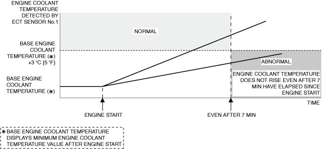
Function Explanation (DTC Detection Outline)
• If the engine coolant temperature detected by the ECT sensor No.1 is not rising 3 °C {5 °F} or more during a 7 min period after the engine is started, the PCM determines an ECT sensor No.1 malfunction and stores a DTC.
am3zzw00033342
|
Repeatability Verification Procedure
1. Start the engine and leave it idling for 10 s.
2. Switch the ignition off.
3. Leave the vehicle for 6 hours or more.
4. Start the engine and leave it idling for 8 min.
PID Item/Simulation Item Used In Diagnosis
PID/DATA monitor item table
|
PIDs |
Reference |
|---|---|
|
ECT
|
|
|
ECT_VOLT
|
Function Inspection Using M-MDS
|
Step |
Inspection |
Results |
Action |
|---|---|---|---|
|
1
|
PURPOSE: VERIFY RELATED REPAIR INFORMATION OR SERVICE INFORMATION AVAILABILITY
• Verify related Service Bulletins, on-line repair information, or Service Information availability.
• Is any related Information available?
|
Yes
|
Perform repair or diagnosis according to the available information.
• If the vehicle is not repaired, go to the next step.
|
|
No
|
Go to the next step.
|
||
|
2
|
PURPOSE: RECORD VEHICLE STATUS WHEN DTC WAS DETECTED TO UTILIZE WITH REPEATABILITY VERIFICATION
• Record the freeze frame data/snapshot data.
|
—
|
Go to the next step.
|
|
3
|
PURPOSE: VERIFY CONNECTOR CONNECTIONS
• Start the engine.
• Access the ECT PID using the M-MDS. (See PID/DATA MONITOR INSPECTION.)
• Does the PID value fluctuate when the following connectors are shaken?
|
Yes
|
Repair or replace the applicable connector parts.
Go to Troubleshooting Diagnostic Procedure to perform the repair completion verification.
|
|
No
|
Go to the next step.
|
||
|
4
|
PURPOSE: VERIFY ECT SENSOR No.1 INPUT SIGNAL
• Access the ECT PID using the M-MDS. (See PID/DATA MONITOR INSPECTION.)
• Is the PID value within specification?
|
Yes
|
Go to Troubleshooting Diagnostic Procedure to perform the procedure from Step 3.
|
|
No
|
Go to Troubleshooting Diagnostic Procedure to perform the procedure from Step 1.
|
Troubleshooting Diagnostic Procedure
Intention of troubleshooting procedure
• Step 1—2
-
― Perform an ECT sensor No.1-related inspection.
• Step 3—5
-
― Perform an engine coolant-related inspection.
• Step 6
-
― Perform a unit inspection of the coolant control valve.
• Repair completion verification
-
― Verify that the primary malfunction is resolved and there are no other malfunctions.
|
Step |
Inspection |
Results |
Action |
|---|---|---|---|
|
1
|
PURPOSE: VERIFY IF ECT SENSOR No.1 IS INSTALLED CORRECTLY
• Verify the ECT sensor No.1 installation condition. (See ENGINE COOLANT TEMPERATURE (ECT) SENSOR REMOVAL/INSTALLATION [SKYACTIV-G (WITH CYLINDER DEACTIVATION (US))].) (See ENGINE COOLANT TEMPERATURE (ECT) SENSOR REMOVAL/INSTALLATION [SKYACTIV-G (WITHOUT CYLINDER DEACTIVATION (US))].)
• Is the installation condition normal?
|
Yes
|
Go to the next step.
|
|
No
|
Correctly install the ECT sensor No.1 and perform the repair completion verification.
|
||
|
2
|
PURPOSE: INSPECT ECT SENSOR No.1 FOR MALFUNCTION
• Inspect the applicable part. (See ENGINE COOLANT TEMPERATURE (ECT) SENSOR INSPECTION [SKYACTIV-G (WITH CYLINDER DEACTIVATION (US))].) (See ENGINE COOLANT TEMPERATURE (ECT) SENSOR INSPECTION [SKYACTIV-G (WITHOUT CYLINDER DEACTIVATION (US))].)
• Is the part normal?
|
Yes
|
Go to the next step.
|
|
No
|
Repair or replace the malfunctioning location and perform the repair completion verification.
|
||
|
3
|
PURPOSE: VERIFY IF MALFUNCTION CAUSED BY POOR ENGINE COOLANT PASSAGE ASSEMBLY
• Verify the connection condition of the engine coolant passage (such as hoses). (See COOLING SYSTEM LOCATION INDEX [SKYACTIV-G (WITH CYLINDER DEACTIVATION (US))].) (See COOLING SYSTEM LOCATION INDEX [SKYACTIV-G (WITHOUT CYLINDER DEACTIVATION (US))].)
• Is there any malfunction?
|
Yes
|
Reconnect the engine coolant passage correctly.
Replace the engine coolant and perform the repair completion verification.
|
|
No
|
Go to the next step.
|
||
|
4
|
PURPOSE: VERIFY IF MALFUNCTION RELATED TO ENGINE COOLANT AFFECTS DIAGNOSTIC RESULTS
• Inspect the following:
• Are all items normal?
|
Yes
|
Go to the next step.
|
|
No
|
Replace the engine coolant and perform the repair completion verification. (Advise the customer to use specified engine coolant used.)
|
||
|
5
|
PURPOSE: VERIFY IF MALFUNCTION RELATED TO ENGINE COOLANT LEAKAGE FROM ENGINE COOLANT PASSAGE AFFECTS DIAGNOSTIC RESULTS
• Perform the “ENGINE COOLANT LEAKAGE INSPECTION”. (See ENGINE COOLANT LEAKAGE INSPECTION [SKYACTIV-G (WITH CYLINDER DEACTIVATION (US))].) (See ENGINE COOLANT LEAKAGE INSPECTION [SKYACTIV-G (WITHOUT CYLINDER DEACTIVATION (US))].)
• Is there engine coolant leaking from the engine coolant passage?
|
Yes
|
Repair or replace the malfunctioning location and refill the system with engine coolant.
Go to repair completion verification.
|
|
No
|
Go to the next step.
|
||
|
6
|
PURPOSE: INSPECT COOLANT CONTROL VALVE FOR MALFUNCTION
• Inspect the applicable part. (See COOLANT CONTROL VALVE INSPECTION [SKYACTIV-G (WITH CYLINDER DEACTIVATION (US))].) (See COOLANT CONTROL VALVE INSPECTION [SKYACTIV-G (WITHOUT CYLINDER DEACTIVATION (US))].)
• Is the part normal?
|
Yes
|
Go to the next step.
|
|
No
|
Repair or replace the malfunctioning location and perform the repair completion verification.
|
||
|
Repair completion verification 1
|
PURPOSE: VERIFY THAT VEHICLE IS REPAIRED
• Install/connect the part removed/disconnected during the troubleshooting procedure.
• Clear the DTC recorded in the memory. (See CLEARING DTC.)
• Replicate the vehicle conditions at the time the DTC was detected using the following procedure.
• Perform the DTC inspection for the PCM. (See DTC INSPECTION.)
• Is the same Pending DTC present?
|
Yes
|
Refer to the controller area network (CAN) malfunction diagnosis flow to inspect for a CAN communication error.
If the CAN communication is normal, perform the diagnosis from Step 1.
• If the malfunction recurs, replace the PCM, then go to the next step. (See PCM REMOVAL/INSTALLATION [SKYACTIV-G (WITH CYLINDER DEACTIVATION (US))].) (See PCM REMOVAL/INSTALLATION [SKYACTIV-G (WITHOUT CYLINDER DEACTIVATION (US))].)
|
|
No
|
Go to the next step.
|
||
|
Repair completion verification 2
|
PURPOSE: VERIFY IF OTHER DTCs DISPLAYED
• Perform the DTC inspection. (See DTC INSPECTION.)
• Are any other DTCs displayed?
|
Yes
|
Repair the malfunctioning location according to the applicable DTC troubleshooting.
|
|
No
|
DTC troubleshooting completed.
|