NO.3 BRAKE SYSTEM WARNING LIGHT STAY ON [DYNAMIC STABILITY CONTROL (DSC)]
NO.3 BRAKE SYSTEM WARNING LIGHT STAY ON [DYNAMIC STABILITY CONTROL (DSC)]
SM2335153
id0403b2895800
|
Troubleshooting item |
Brake system warning lights stay on |
|
|---|---|---|
|
Possible cause
|
• Brake fluid amount is low.
• Brake fluid level sensor stuck on.
• Short to ground in fluid level sensor signal circuit.
• No connection at DSC HU/CM connector (When DSC HU/CM connector comes off, ABS warning light, brake system warning light, DSC indicator light, and DSC OFF indicator light illuminate.)
• DSC HU/CM detected malfunction. (Input and output device malfunction)
• DSC HU/CM detects low voltage in power supply.
• DSC HU/CM ground malfunction (When DSC HU/CM ground is not securely connected, ABS warning light, brake system warning light, DSC indicator light, and DSC OFF indicator light illuminate but diagnostic trouble code does not display.)
• DSC HU/CM does not operate.
• DSC HU/CM internal malfunction
• Instrument cluster detected malfunction
|
|
 |
||
 |
||
 |
||
Diagnostic procedure
|
Step |
Inspection |
Results |
Action |
|---|---|---|---|
|
1
|
INSPECT BRAKE FLUID AMOUNT AND VERIFY THAT ELECTRIC PARKING BRAKE RELEASED
• Inspect the brake fluid amount and verify that the electric parking brake released.
• Is the brake fluid amount normal?
• Is the electric parking brake released?
|
Yes
|
Go to the next step.
|
|
No
|
Add the brake fluid or release the electric parking brake.
If the brake fluid refilled:
• Inspect and repair the brake line for leakage.
Perform the repair completion verification.
|
||
|
2
|
CONFIRM DSC HU/CM DTC
• Retrieve the DSC HU/CM DTC using the M-MDS. (See DTC INSPECTION.)
• Are any DTCs present?
|
Yes
|
Go to the applicable DTC inspection.
(See DTC TABLE [DSC HU/CM (US)].)
|
|
No
|
If communication error message is displayed on the M-MDS screen:
• Go to the next step.
If communication error message is not displayed:
• Go to Step 4.
|
||
|
3
|
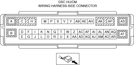
INSPECT CONNECTION OF DSC HU/CM CONNECTOR
• Inspect for connection of the DSC HU/CM connector.
• Is the DSC HU/CM connector connected securely?
|
Yes
|
Go to the next step.
|
|
No
|
Connect the DSC HU/CM connector securely, then go to the next step.
|
||
|
4
|
VERIFY IF THE BRAKE SYSTEM WARNING LIGHT IS TURNED OFF
• Switch the ignition ON (engine off or on).
• Press down the electric parking brake switch to release the electric parking brake.
• Does the brake system warning light turn off?
|
Yes
|
Go to Step 7.
|
|
No
|
Go to the next step.
|
||
|
5
|
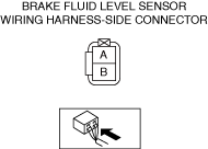
INSPECT WHETHER MALFUNCTION IS IN BRAKE FLUID LEVEL SENSOR OR ELSEWHERE
• Inspect the brake fluid level sensor for continuity. (See BRAKE FLUID LEVEL SENSOR INSPECTION [(US)].)
• Is the continuity condition normal?
|
Yes
|
Go to the next step.
|
|
No
|
Replace the malfunctioning part, and perform the repair completion verification.
|
||
|
*6
|
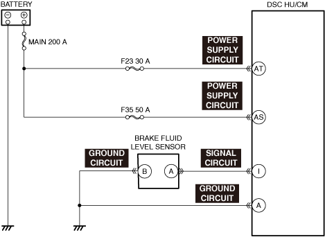
INSPECT BRAKE FLUID LEVEL SENSOR SIGNAL CIRCUIT FOR SHORT TO GROUND
• Inspect the signal circuit for a short to ground. (See CIRCUIT INSPECTION.)
• Is the circuit normal?
|
Yes
|
Replace the instrument cluster, and perform the repair completion verification.
|
|
No
|
Repair or replace the malfunctioning location, and perform the repair completion verification.
|
||
|
*7
|
INSPECT DSC HU/CM POWER SUPPLY CIRCUIT FOR SHORT TO GROUND AND OPEN CIRCUIT
• Inspect the power supply circuit for an open circuit and short to ground. (See CIRCUIT INSPECTION.)
• Is the circuit normal?
|
Yes
|
Go to the next step.
|
|
No
|
Repair or replace the malfunctioning location, and perform the repair completion verification.
|
||
|
*8
|
INSPECT DSC HU/CM GROUND CIRCUIT FOR SHORT TO POWER SUPPLY AND OPEN CIRCUIT
• Inspect the ground circuit for an open circuit and short to power supply. (See CIRCUIT INSPECTION.)
• Is the circuit normal?
|
Yes
|
Replace the DSC HU/CM, and perform the repair completion verification. (open circuit in the DSC HU/CM)
|
|
No
|
Repair or replace the malfunctioning location, and perform the repair completion verification.
|
||
|
Repair completion verification
|
VERIFY THAT MALFUNCTION SYMPTOMS DO NOT RECUR AFTER REPAIR
• Install/connect the part removed/disconnected during the troubleshooting procedure.
• Has the malfunction symptom been eliminated?
|
Yes
|
Complete the symptom troubleshooting.
Explain to the customer what has been repaired.
|
|
No
|
Refer to the controller area network (CAN) malfunction diagnosis flow to inspect for a CAN communication error.
If the CAN communication is normal, perform the diagnosis from Step 1.
|
• When performing an asterisked (*) troubleshooting inspection, shake the wiring harness and connectors while doing the inspection to discover whether poor contact points are the cause of any intermittent malfunctions. If there is a problem, check to make sure connectors, terminals and wiring harness are connected correctly and undamaged.