BRAKE FLUID LEVEL SENSOR INSPECTION [(US)]
BRAKE FLUID LEVEL SENSOR INSPECTION [(US)]
SM2565962
id0411008014xa
1.Disconnect the negative battery terminal.
(See NEGATIVE BATTERY TERMINAL DISCONNECTION/CONNECTION [(US)].)
2.Remove the following parts as a single unit.
(See INTAKE-AIR SYSTEM REMOVAL/INSTALLATION [SKYACTIV-G (WITHOUT CYLINDER DEACTIVATION (US))].) (See INTAKE-AIR SYSTEM REMOVAL/INSTALLATION [SKYACTIV-G (WITH CYLINDER DEACTIVATION (US))].)
-
• Air hose• Air cleaner cover• Air cleaner element• Air cleaner case• Fresh-air duct• Resonance chamber
3.Remove the battery.
(See BATTERY REMOVAL/INSTALLATION [SKYACTIV-G (WITHOUT CYLINDER DEACTIVATION (US))].) (See BATTERY REMOVAL/INSTALLATION [SKYACTIV-G (WITH CYLINDER DEACTIVATION (US))].)
4.Remove the Battery tray and PCM component.
(See BATTERY REMOVAL/INSTALLATION [SKYACTIV-G (WITHOUT CYLINDER DEACTIVATION (US))].) (See BATTERY REMOVAL/INSTALLATION [SKYACTIV-G (WITH CYLINDER DEACTIVATION (US))].) (See PCM REMOVAL/INSTALLATION [SKYACTIV-G (WITHOUT CYLINDER DEACTIVATION (US))].) (See PCM REMOVAL/INSTALLATION [SKYACTIV-G (WITH CYLINDER DEACTIVATION (US))].)
5.Set the PCM wiring harness out of the way.
6.Disconnect the vacuum hose from the clip.
(See VACUUM HOSE REMOVAL/INSTALLATION [SKYACTIV-G (WITHOUT CYLINDER DEACTIVATION (US))].) (See VACUUM HOSE REMOVAL/INSTALLATION [SKYACTIV-G (WITH CYLINDER DEACTIVATION (US))].)
7.Disconnect the brake fluid level sensor connector.
(See MASTER CYLINDER REMOVAL/INSTALLATION [L.H.D. (US)].)
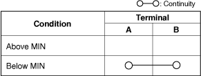
8.Inspect for continuity according to fluid level between the brake fluid level sensor terminals.
am3zzw00035278
|

am6xuw00010661
|
-
• If not as indicated in the table, replace the reserve tank. (See MASTER CYLINDER REMOVAL/INSTALLATION [L.H.D. (US)].)