DTC C0039:07, C003A:07, C003A:29, C003A:2F, C003A:37 OR C003A:64 [DSC HU/CM]
DTC C0039:07, C003A:07, C003A:29, C003A:2F, C003A:37 OR C003A:64 [DSC HU/CM]
SM2335038
id040262004500
-
Note
-
• When only the driving wheels are rotated while the vehicle is jacked up, DTCs C0037:29 and C003A:29 are input to the memory.
Outline
|
System malfunction location |
DTC C0039:07 |
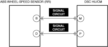
ABS wheel-speed sensor (RR) |
|||
|---|---|---|---|---|---|
|
DTC C003A:07, C003A:29, C003A:2F, C003A:37 or C003A:64 |
ABS wheel-speed sensor (RR), ABS wheel-speed sensor rotor |
||||
|
Detection condition
|
• C0039:07
• C003A:07
• C003A:29
• C003A:2F
• C003A:37
• C003A:64
|
||||
|
Fail-safe
|
Refer to “DTC Table” and “Fail-safe Function Malfunction Contents Table”. (See DTC TABLE [DSC HU/CM (US)].)
|
||||
|
Possible cause
|
• Continuous ABS operation
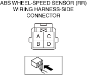
• ABS wheel-speed sensor (RR) connector or terminals malfunction
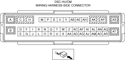
• DSC HU/CM connector or terminals malfunction
• ABS sensor rotor malfunction (missing ABS sensor rotor teeth due to foreign material obstruction)
• ABS wheel-speed sensor (RR) or ABS sensor rotor installation malfunction (If the ABS sensor rotor is installed at an angle, it may cause output of abnormal wave pattern at high speeds.)
• Excessive clearance between the ABS wheel-speed sensor and sensor rotor
• ABS wheel-speed sensor (RR) malfunction
• DSC HU/CM malfunction
|
||||
 |
|||||
 |
|||||
 |
|||||
Diagnostic Procedure
|
Step |
Inspection |
Results |
Action |
|---|---|---|---|
|
1
|
VERIFY THAT THERE IS NO ABS WHEEL-SPEED SENSOR OUTPUT MALFUNCTION
• Select the following PIDs. (See PID/DATA MONITOR INSPECTION.) (See PID/DATA MONITOR TABLE [DSC HU/CM].)
• Drive the vehicle.
• Verify that the vehicle speeds detected by the four ABS wheel-speed sensors are approximately the same.
• Are the vehicle speeds approximately the same?
|
Yes
|
Go to Step 4.
|
|
No
|
Go to the next step.
|
||
|
2
|
INSPECT ABS WHEEL-SPEED SENSOR (RR) CONNECTOR FOR MALFUNCTION
• Inspect the applicable connector and terminal. (See CONNECTOR INSPECTION.)
• Are the connector and terminal normal?
|
Yes
|
Go to the next step.
|
|
No
|
Repair or replace the malfunctioning location and perform the repair completion verification.
|
||
|
3
|
INSPECT DSC HU/CM CONNECTOR FOR MALFUNCTION
• Inspect the applicable connector and terminal. (See CONNECTOR INSPECTION.)
• Are the connector and terminal normal?
|
Yes
|
Go to the next step.
|
|
No
|
Repair or replace the malfunctioning location and perform the repair completion verification.
|
||
|
4
|
INSPECT IF MALFUNCTION OCCURRED DUE TO IMPROPER SENSOR CLEARANCE
• Inspect the clearance between the ABS wheel-speed sensor and the ABS sensor rotor. (See REAR ABS WHEEL-SPEED SENSOR INSPECTION [2WD].) (See REAR ABS WHEEL-SPEED SENSOR INSPECTION [AWD].)
• Is the clearance normal?
|
Yes
|
Go to the next step.
|
|
No
|
Replace the ABS wheel-speed sensor (RR) and perform the repair completion verification.
|
||
|
5
|
VISUALLY INSPECT ABS SENSOR ROTOR FOR FOREIGN MATERIAL ADHERING OR IMPROPER INSTALLATION
• Visually inspect for ABS sensor rotor. (See WHEEL HUB COMPONENT REMOVAL/INSTALLATION [2WD].) (See REAR DRIVE SHAFT REMOVAL/INSTALLATION.)
• Is there foreign matter on the ABS sensor rotor?
|
Yes
|
Repair or replace the ABS sensor rotor and perform the repair completion verification.
|
|
No
|
Go to the next step.
|
||
|
Repair completion verification 1
|
VERIFY THAT VEHICLE IS REPAIRED
• Install/connect the part removed/disconnected during the troubleshooting procedure.
• Clear the DTC recorded in the memory. (See CLEARING DTC.)
• Start the engine and drive the vehicle at 20 km/h {12 mph} or more.
• Perform the DTC inspection for the DSC HU/CM. (See DTC INSPECTION.)
• Is the same Pending DTC present?
|
Yes
|
Refer to the controller area network (CAN) malfunction diagnosis flow to inspect for a CAN communication error.
If the CAN communication is normal, perform the diagnosis from Step 1.
• If the malfunction recurs, replace the DSC HU/CM, then go to the next step. (See DSC HU/CM REMOVAL/INSTALLATION [L.H.D. (US)].)
|
|
No
|
Go to the next step.
|
||
|
Repair completion verification 2
|
VERIFY IF OTHER DTCs DISPLAYED
• Perform the DTC inspection. (See DTC INSPECTION.)
• Are any DTCs displayed?
|
Yes
|
Repair the malfunctioning location according to the applicable DTC troubleshooting.
|
|
No
|
DTC troubleshooting completed.
|