DTC P250A:00 [PCM (SKYACTIV-G)]
DTC P250A:00 [PCM (SKYACTIV-G)]
SM2334560
id0102t4787200
-
Note
-
• To determine the malfunctioning part, proceed with the diagnostics from “Function Inspection Using M-MDS”.
Details On DTCs
|
Description |
Engine oil level signal: engine oil level sensor malfunction |
||
|---|---|---|---|
|
Detection condition
|
Determination conditions
|
• PCM receives abnormal signal from the engine oil level sensor.
• If the engine oil level signal from the engine oil level sensor does not change, an oil level change due to driving conditions can be considered.
|
|
|
Preconditions
|
• Battery voltage: 10—16 V *1
• The following DTC is not detected:
• Low-G (XY) sensor (built-into SAS control module) signal is normal
*1: Standard can be verified by displaying PIDs using M-MDS
|
||
|
Drive cycle
|
• 1
|
||
|
Self test type
|
• CMDTC self test
|
||
|
Sensor used
|
• Engine oil level sensor
• Engine oil temperature sensor
• Low-G (XY) sensor (built-into SAS control module)
|
||
|
Fail-safe function
|
• Not applicable
|
||
|
Vehicle status when DTCs are output
|
• Not applicable
|
||
|
Possible cause
|
• Engine oil level sensor malfunction
• Erratic signal to PCM
• PCM malfunction
|
||
 |
|||
 |
 |
||
 |
|||
 |
|||
Function Explanation (DTC Detection Outline)
• The PCM receives the signal from the engine oil level sensor and diagnoses the following malfunctions.
-
― The engine oil temperature is −35 °C {−31 °F} or more and an error signal on the engine oil temperature side from the engine oil level sensor is received continuously for 30 s or more.― A sensor malfunction signal from the engine oil level sensor is received continuously for 30 s or more.
• The PCM performs diagnosis when each of the preconditions is met during a drive cycle. If any of the above malfunctions is detected, a malfunction is determined, DTCs are stored and the engine oil level warning light is turned on.
• The PCM performs diagnosis when each of the preconditions is met during a drive cycle. If any of the above malfunctions is detected, a malfunction is determined, DTCs are stored and the master warning indication or engine oil level warning indication is displayed on the multi-information display.
Repeatability Verification Procedure
1. Start the engine and run it at idle.
PID Item/Simulation Item Used In Diagnosis
PID/DATA monitor item table
|
PIDs |
Reference |
|---|---|
|
ENG_OIL_LVL
|
Function Inspection Using M-MDS
|
Step |
Inspection |
Results |
Action |
|---|---|---|---|
|
1
|
PURPOSE: RECORD VEHICLE STATUS WHEN DTC WAS DETECTED TO UTILIZE WITH REPEATABILITY VERIFICATION
• Record the freeze frame data/snapshot data.
|
—
|
Go to the next step.
|
|
2
|
PURPOSE: VERIFY RELATED REPAIR INFORMATION OR SERVICE INFORMATION AVAILABILITY
• Verify related Service Bulletins, on-line repair information, or Service Information availability.
• Is any related Information available?
|
Yes
|
Perform repair or diagnosis according to the available information.
• If the vehicle is not repaired, go to the next step.
|
|
No
|
Go to the next step.
|
||
|
3
|
PURPOSE: IDENTIFY TRIGGER DTC FOR FREEZE FRAME DATA
• Is the DTC P250A:00 on freeze frame data?
|
Yes
|
Go to the next step.
|
|
No
|
Go to the troubleshooting procedure for DTC on freeze frame data.
|
||
|
4
|
PURPOSE: INSPECT FOR OTHER RELATED DTCs
• Perform the DTC inspection for the PCM. (See DTC INSPECTION.)
• Are any other DTCs displayed?
|
Yes
|
Repair the malfunctioning location according to the applicable DTC troubleshooting.
|
|
No
|
Go to the next step.
|
||
|
5
|
PURPOSE: VERIFY IF THERE IS PID ITEM CAUSING DRASTIC CHANGES OF ACCELERATION FLUCTUATION BY INPUT SIGNAL TO PCM
• Access the following PIDs using the M-MDS: (See PID/DATA MONITOR INSPECTION.)
• Is the PID value within specification? (See ENGINE OIL LEVEL SENSOR INSPECTION [SKYACTIV-G (WITH CYLINDER DEACTIVATION (US))].) (See ENGINE OIL LEVEL SENSOR INSPECTION [SKYACTIV-G (WITHOUT CYLINDER DEACTIVATION (US))].)
|
Yes
|
Go to the next step.
|
|
No
|
Go to Troubleshooting Diagnostic Procedure to perform the procedure from Step 1.
|
||
|
6
|
PURPOSE: VERIFY CONNECTOR CONNECTIONS
• Access the following PIDs using the M-MDS: (See PID/DATA MONITOR INSPECTION.)
• When the following parts are shaken, does the PID value include a PID item which has changed?
|
Yes
|
Repair or replace the applicable connector parts.
Go to Troubleshooting Diagnostic Procedure to perform the repair completion verification.
|
|
No
|
Go to Troubleshooting Diagnostic Procedure to perform the procedure from Step 1.
|
Troubleshooting Diagnostic Procedure
Intention of troubleshooting procedure
• Step 1
-
― Inspect for clogging of the oil passage to the engine oil level sensor detection area.
• Step 2—4
-
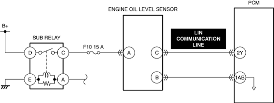
― Perform an inspection of LIN communication line.
• Repair completion verification
-
― Verify that the primary malfunction is resolved and there are no other malfunctions.
|
Step |
Inspection |
Results |
Action |
|---|---|---|---|
|
1
|
PURPOSE: INSPECT FOR CLOGGING OF THE OIL PASSAGE TO THE ENGINE OIL LEVEL SENSOR DETECTION AREA
• Remove the engine oil level sensor. (See ENGINE OIL LEVEL SENSOR REMOVAL/INSTALLATION [SKYACTIV-G (WITH CYLINDER DEACTIVATION (US))].) (See ENGINE OIL LEVEL SENSOR REMOVAL/INSTALLATION [SKYACTIV-G (WITHOUT CYLINDER DEACTIVATION (US))].)
• Visually inspect the oil passage to the engine oil level sensor.
• Is there any restriction detected?
|
Yes
|
Clean the oil passage and perform the repair completion verification.
|
|
No
|
Go to the next step.
|
||
|
2
|
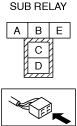
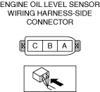
PURPOSE: INSPECT ENGINE OIL LEVEL SENSOR CONNECTOR FOR MALFUNCTION
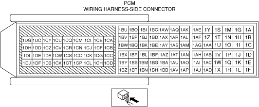
• Inspect the applicable connector and terminal. (See CONNECTOR INSPECTION.)
• Are the connector and terminal normal?
|
Yes
|
Go to the next step.
|
|
No
|
Repair or replace the malfunctioning location and perform the repair completion verification.
|
||
|
3
|
PURPOSE: INSPECT LIN COMMUNICATION LINE FOR SHORT TO GROUND
• Inspect the applicable circuit for a short to ground. (See CIRCUIT INSPECTION.)
• Is the circuit normal?
|
Yes
|
Go to the next step.
|
|
No
|
Repair or replace the malfunctioning location and perform the repair completion verification.
|
||
|
4
|
PURPOSE: INSPECT LIN COMMUNICATION LINE FOR OPEN CIRCUIT
• Inspect the applicable circuit for open circuit. (See CIRCUIT INSPECTION.)
• Is the circuit normal?
|
Yes
|
Replace the engine oil level sensor and perform the repair completion verification.
|
|
No
|
Repair or replace the malfunctioning location and perform the repair completion verification.
|
||
|
Repair completion verification 1
|
PURPOSE: VERIFY THAT VEHICLE IS REPAIRED
• Install/connect the part removed/disconnected during the troubleshooting procedure.
• Clear the DTC recorded in the memory. (See CLEARING DTC.)
• Replicate the vehicle conditions at the time the DTC was detected using the following procedure.
• Perform the DTC inspection for the PCM. (See DTC INSPECTION.)
• Is the same Pending DTC present?
|
Yes
|
Refer to the controller area network (CAN) malfunction diagnosis flow to inspect for a CAN communication error.
If the CAN communication is normal, perform the diagnosis from Step 1.
• If the malfunction recurs, replace the PCM, then go to the next step. (See PCM REMOVAL/INSTALLATION [SKYACTIV-G (WITH CYLINDER DEACTIVATION (US))].) (See PCM REMOVAL/INSTALLATION [SKYACTIV-G (WITHOUT CYLINDER DEACTIVATION (US))].)
|
|
No
|
Go to the next step.
|
||
|
Repair completion verification 2
|
PURPOSE: VERIFY IF OTHER DTCs DISPLAYED
• Perform the DTC inspection. (See DTC INSPECTION.)
• Are any other DTCs displayed?
|
Yes
|
Repair the malfunctioning location according to the applicable DTC troubleshooting.
|
|
No
|
DTC troubleshooting completed.
|