DTC P0806:00 [PCM (SKYACTIV-G)]
DTC P0806:00 [PCM (SKYACTIV-G)]
SM2334498
id0102t4606700
Outline
|
System malfunction location |
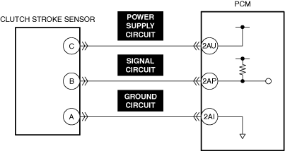
Clutch stroke sensor input circuit problem |
||||
|---|---|---|---|---|---|
|
Detection condition
|
• The PCM monitors changes in input voltage from the clutch stroke sensor. If the PCM does not detect a voltage change while the vehicle runs with vehicle speed above 30 km/h {19 mph} and stops 8 times alternately, the PCM determines that the clutch stroke sensor circuit has a malfunction.
|
||||
|
Fail-safe
|
• Not applicable
|
||||
|
Possible cause
|
• Clutch stroke sensor connector or terminals malfunction
• PCM connector or terminals malfunction
• Short to ground in any of the following clutch stroke sensor circuits.
• Short to power supply in any of the following clutch stroke sensor circuits.
• Open circuit in any of the following clutch stroke sensor circuits.
• Clutch stroke sensor malfunction
• Driver continues to depress clutch pedal causing mistaken detection by PCM
• PCM malfunction
|
||||
 |
|||||
 |
 |
||||
Diagnostic Procedure
|
Step |
Inspection |
Results |
Action |
|---|---|---|---|
|
1
|
RECORD VEHICLE STATUS WHEN DTC WAS DETECTED TO UTILIZE WITH REPEATABILITY VERIFICATION
• Record the freeze frame data/snapshot data.
|
—
|
Go to the next step.
|
|
2
|
VERIFY RELATED REPAIR INFORMATION OR SERVICE INFORMATION AVAILABILITY
• Verify related Service Bulletins, on-line repair information, or Service Information availability.
• Is any related Information available?
|
Yes
|
Perform repair or diagnosis according to the available information.
• If the vehicle is not repaired, go to the next step.
|
|
No
|
Go to the next step.
|
||
|
3
|
INSPECT CLUTCH STROKE SENSOR CONNECTOR FOR MALFUNCTION
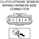
• Inspect the applicable connector and terminal. (See CONNECTOR INSPECTION.)
• Are the connector and terminal normal?
|
Yes
|
Go to the next step.
|
|
No
|
Repair or replace the malfunctioning location and perform the repair completion verification.
|
||
|
4
|
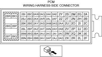
INSPECT PCM CONNECTOR FOR MALFUNCTION
• Inspect the applicable connector and terminal. (See CONNECTOR INSPECTION.)
• Are the connector and terminal normal?
|
Yes
|
Go to the next step.
|
|
No
|
Repair or replace the malfunctioning location and perform the repair completion verification.
|
||
|
5
|
INSPECT CLUTCH STROKE SENSOR POWER SUPPLY CIRCUIT AND SIGNAL CIRCUIT FOR SHORT TO GROUND
• Inspect the applicable circuit for a short to ground. (See CIRCUIT INSPECTION.)
• Is the circuit normal?
|
Yes
|
Go to the next step.
|
|
No
|
Repair or replace the malfunctioning location and perform the repair completion verification.
|
||
|
6
|
INSPECT CLUTCH STROKE SENSOR SIGNAL CIRCUIT AND GROUND CIRCUIT FOR SHORT TO POWER SUPPLY
• Inspect the applicable circuit for a short to power supply. (See CIRCUIT INSPECTION.)
• Is the circuit normal?
|
Yes
|
Go to the next step.
|
|
No
|
Repair or replace the malfunctioning location and perform the repair completion verification.
|
||
|
7
|
INSPECT CLUTCH STROKE SENSOR POWER SUPPLY CIRCUITS, SIGNAL CIRCUITS, AND GROUND CIRCUITS FOR OPEN CIRCUIT
• Inspect the applicable circuit for open circuit. (See CIRCUIT INSPECTION.)
• Is the circuit normal?
|
Yes
|
Go to the next step.
|
|
No
|
Repair or replace the malfunctioning location and perform the repair completion verification.
|
||
|
8
|
INSPECT CLUTCH STROKE SENSOR FOR MALFUNCTION
• Inspect the applicable part. (See CLUTCH STROKE SENSOR INSPECTION [SKYACTIV-G (WITH CYLINDER DEACTIVATION (US))].) (See CLUTCH STROKE SENSOR INSPECTION [SKYACTIV-G (WITHOUT CYLINDER DEACTIVATION (US))].)
• Is the part normal?
|
Yes
|
Go to the next step.
|
|
No
|
Repair or replace the malfunctioning location and perform the repair completion verification.
|
||
|
9
|
VERIFY THAT THERE IS NO PROBLEM WITH CUSTOMER CLUTCH PEDAL OPERATION
• Is the clutch pedal depressed after operating the shift lever during a traffic jam?
|
Yes
|
Explain to the customer that it is necessary to remove the foot from the clutch pedal completely after operating the shift lever.
Go to repair completion verification.
|
|
No
|
Go to the next step.
|
||
|
Repair completion verification 1
|
VERIFY THAT VEHICLE IS REPAIRED
• Install/connect the part removed/disconnected during the troubleshooting procedure.
• Clear the DTC recorded in the memory. (See CLEARING DTC.)
• Replicate the vehicle conditions at the time the DTC was detected using the following procedure.
• Perform the DTC inspection for the PCM. (See DTC INSPECTION.)
• Is the same Pending DTC present?
|
Yes
|
Refer to the controller area network (CAN) malfunction diagnosis flow to inspect for a CAN communication error.
If the CAN communication is normal, perform the diagnosis from Step 1.
• If the malfunction recurs, replace the PCM, then go to the next step. (See PCM REMOVAL/INSTALLATION [SKYACTIV-G (WITH CYLINDER DEACTIVATION (US))].) (See PCM REMOVAL/INSTALLATION [SKYACTIV-G (WITHOUT CYLINDER DEACTIVATION (US))].)
|
|
No
|
Go to the next step.
|
||
|
Repair completion verification 2
|
VERIFY IF OTHER DTCs DISPLAYED
• Perform the DTC inspection. (See DTC INSPECTION.)
• Are any other DTCs displayed?
|
Yes
|
Repair the malfunctioning location according to the applicable DTC troubleshooting.
|
|
No
|
DTC troubleshooting completed.
|