DTC P0110:00 [PCM (SKYACTIV-G)]
DTC P0110:00 [PCM (SKYACTIV-G)]
SM2334361
id0102t4003600
-
Note
-
• To determine the malfunctioning part, proceed with the diagnostics from “Function Inspection Using M-MDS”.
Details On DTCs
|
Description |
IAT sensor No.1 circuit internal malfunction |
||
|---|---|---|---|
|
Detection condition
|
Determination conditions
|
• Any one of the following conditions is met:
|
|
|
Preconditions
|
• The following DTC is not detected:
|
||
|
Drive cycle
|
• 1
|
||
|
Self test type
|
• CMDTC self test, KOEO self test, KOER self test
|
||
|
Sensor used
|
• MAF sensor/IAT sensor No.1
|
||
|
Fail-safe function
|
• Restricts the upper limit of the engine speed.
• Inhibits the evaporative purge control.
|
||
|
Vehicle status when DTCs are output
|
• Rough idling, poor acceleration, stalling
|
||
|
Possible cause
|
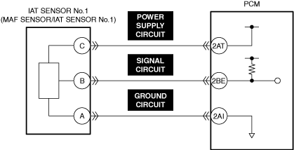
• MAF sensor/IAT sensor No.1 incorrect installation
• MAF sensor/IAT sensor No.1 connector or terminals malfunction
• PCM connector or terminals malfunction
• Short to ground in any of the following MAF sensor/IAT sensor No.1 circuits.
• Open circuit in any of the following MAF sensor/IAT sensor No.1 circuits.
• Short to power supply in MAF sensor/IAT sensor No.1 signal circuit
• Short circuit between any of the following MAF sensor/IAT sensor No.1 circuits.
• MAF sensor/IAT sensor No.1 malfunction
• PCM malfunction
|
||
 |
|||
 |
|||
 |
|||
Function Explanation (DTC Detection Outline)
• When there is an internal malfunction in IAT sensor No.1, the MAF sensor/IAT sensor No.1 sends a malfunction signal to the PCM. When the PCM receives a malfunction signal from the MAF sensor/IAT sensor No.1, the MAF sensor/IAT sensor No.1 determines an internal malfunction and stores a DTC. In addition, when the PCM receives a value other than the preset standard for the output value from IAT sensor No.1 continuously, the PCM determines that there is an internal malfunction in the MAF sensor/IAT sensor No.1 and stores a DTC.
Repeatability Verification Procedure
• Not applicable
PID Item/Simulation Item Used In Diagnosis
PID/DATA monitor item table
|
PIDs |
Reference |
|---|---|
|
MAF
|
|
|
IAT
|
Function Inspection Using M-MDS
|
Step |
Inspection |
Results |
Action |
|---|---|---|---|
|
1
|
PURPOSE: IDENTIFY TRIGGER DTC FOR FREEZE FRAME DATA
• Is the DTC P0110:00 on freeze frame data?
|
Yes
|
Go to the next step.
|
|
No
|
Go to the troubleshooting procedure for DTC on freeze frame data.
|
||
|
2
|
PURPOSE: VERIFY RELATED REPAIR INFORMATION OR SERVICE INFORMATION AVAILABILITY
• Verify related Service Bulletins, on-line repair information, or Service Information availability.
• Is any related Information available?
|
Yes
|
Perform repair or diagnosis according to the available information.
• If the vehicle is not repaired, go to the next step.
|
|
No
|
Go to the next step.
|
||
|
3
|
PURPOSE: RECORD VEHICLE STATUS WHEN DTC WAS DETECTED TO UTILIZE WITH REPEATABILITY VERIFICATION
• Record the freeze frame data/snapshot data.
|
—
|
Go to the next step.
|
|
4
|
PURPOSE: INSPECT FOR OTHER RELATED DTCs
• Perform the DTC inspection for the PCM. (See DTC INSPECTION.)
• Are any other DTCs displayed?
|
Yes
|
Repair the malfunctioning location according to the applicable DTC troubleshooting.
|
|
No
|
Go to the next step.
|
||
|
5
|
PURPOSE: VERIFY MAF SENSOR/IAT SENSOR No.1 INPUT SIGNAL
• Start the engine and idle it.
• Access the following PIDs using the M-MDS: (See PID/DATA MONITOR INSPECTION.)
• Is the PID value within specification?
|
Yes
|
Go to the next step.
|
|
No
|
Go to Troubleshooting Diagnostic Procedure to perform the procedure from Step 1.
|
||
|
6
|
PURPOSE: VERIFY CONNECTOR CONNECTIONS
• Access the following PIDs using the M-MDS: (See PID/DATA MONITOR INSPECTION.)
• Does the PID value fluctuate when the following connectors are shaken?
|
Yes
|
Inspect the related wiring harness and connector.
• Repair or replace the malfunctioning part.
Go to Troubleshooting Diagnostic Procedure to perform the repair completion verification.
|
|
No
|
Go to Troubleshooting Diagnostic Procedure to perform the procedure from Step 1.
|
Troubleshooting Diagnostic Procedure
Intention of troubleshooting procedure
• Step 1—7
-
― Perform an inspection of the connectors and wiring harnesses between the MAF sensor/IAT sensor No.1 and the PCM.
• Step 8
-
― Perform a unit inspection of the MAF sensor/IAT sensor No.1.
• Repair completion verification
-
― Verify that the primary malfunction is resolved and there are no other malfunctions.
|
Step |
Inspection |
Results |
Action |
|---|---|---|---|
|
1
|
PURPOSE: VERIFY IF MAF SENSOR/IAT SENSOR No.1 IS INSTALLED CORRECTLY
• Verify the MAF sensor/IAT sensor No.1 installation condition. (See MASS AIR FLOW (MAF) SENSOR/INTAKE AIR TEMPERATURE (IAT) SENSOR NO.1 REMOVAL/INSTALLATION [SKYACTIV-G (WITH CYLINDER DEACTIVATION (US))].) (See MASS AIR FLOW (MAF) SENSOR/INTAKE AIR TEMPERATURE (IAT) SENSOR NO.1 REMOVAL/INSTALLATION [SKYACTIV-G (WITHOUT CYLINDER DEACTIVATION (US))].)
• Is the installation condition normal?
|
Yes
|
Go to the next step.
|
|
No
|
Correctly install the MAF sensor/IAT sensor No.1 and perform the repair completion verification.
|
||
|
2
|
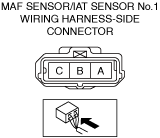
PURPOSE: INSPECT MAF SENSOR/IAT SENSOR No.1 CONNECTOR FOR MALFUNCTION
• Inspect the applicable connector and terminal. (See CONNECTOR INSPECTION.)
• Are the connector and terminal normal?
|
Yes
|
Go to the next step.
|
|
No
|
Repair or replace the malfunctioning location and perform the repair completion verification.
|
||
|
3
|
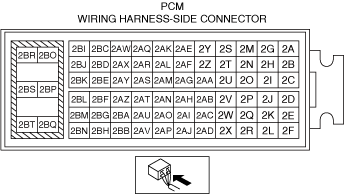
PURPOSE: INSPECT PCM CONNECTOR FOR MALFUNCTION
• Inspect the applicable connector and terminal. (See CONNECTOR INSPECTION.)
• Are the connector and terminal normal?
|
Yes
|
Go to the next step.
|
|
No
|
Repair or replace the malfunctioning location and perform the repair completion verification.
|
||
|
4
|
PURPOSE: INSPECT MAF SENSOR/IAT SENSOR No.1 POWER SUPPLY CIRCUIT AND SIGNAL CIRCUIT FOR SHORT TO GROUND
• Inspect the applicable circuit for a short to ground. (See CIRCUIT INSPECTION.)
• Is the circuit normal?
|
Yes
|
Go to the next step.
|
|
No
|
Repair or replace the malfunctioning location and perform the repair completion verification.
|
||
|
5
|
PURPOSE: INSPECT MAF SENSOR/IAT SENSOR No.1 POWER SUPPLY CIRCUITS, SIGNAL CIRCUITS, AND GROUND CIRCUITS FOR OPEN CIRCUIT
• Inspect the applicable circuit for open circuit. (See CIRCUIT INSPECTION.)
• Is the circuit normal?
|
Yes
|
Go to the next step.
|
|
No
|
Repair or replace the malfunctioning location and perform the repair completion verification.
|
||
|
6
|
PURPOSE: INSPECT MAF SENSOR/IAT SENSOR No.1 SIGNAL CIRCUIT FOR SHORT TO POWER SUPPLY
• Inspect the applicable circuit for a short to power supply. (See CIRCUIT INSPECTION.)
• Is the circuit normal?
|
Yes
|
Go to the next step.
|
|
No
|
Repair or replace the malfunctioning location and perform the repair completion verification.
|
||
|
7
|
PURPOSE: INSPECT MAF SENSOR/IAT SENSOR No.1 POWER SUPPLY CIRCUITS, SIGNAL CIRCUITS, AND GROUND CIRCUITS FOR SHORT CIRCUIT
• Inspect the applicable circuits for a short circuit. (See CIRCUIT INSPECTION.)
• Is the circuit normal?
|
Yes
|
Go to the next step.
|
|
No
|
Repair or replace the malfunctioning location and perform the repair completion verification.
|
||
|
8
|
PURPOSE: INSPECT MAF SENSOR/IAT SENSOR No.1 FOR MALFUNCTION
• Inspect the applicable part. (See MASS AIR FLOW (MAF) SENSOR INSPECTION [SKYACTIV-G (WITH CYLINDER DEACTIVATION (US))].) (See MASS AIR FLOW (MAF) SENSOR INSPECTION [SKYACTIV-G (WITHOUT CYLINDER DEACTIVATION (US))].) (See INTAKE AIR TEMPERATURE (IAT) SENSOR INSPECTION [SKYACTIV-G (WITH CYLINDER DEACTIVATION (US))].) (See INTAKE AIR TEMPERATURE (IAT) SENSOR INSPECTION [SKYACTIV-G (WITHOUT CYLINDER DEACTIVATION (US))].)
• Is the part normal?
|
Yes
|
Go to the next step.
|
|
No
|
Repair or replace the malfunctioning location and perform the repair completion verification.
|
||
|
Repair completion verification 1
|
PURPOSE: VERIFY THAT VEHICLE IS REPAIRED
• Install/connect the part removed/disconnected during the troubleshooting procedure.
• Clear the DTC recorded in the memory. (See CLEARING DTC.)
• Replicate the vehicle conditions at the time the DTC was detected using the following procedure.
• Perform the DTC inspection for the PCM. (See DTC INSPECTION.)
• Is the same Pending DTC present?
|
Yes
|
Refer to the controller area network (CAN) malfunction diagnosis flow to inspect for a CAN communication error.
If the CAN communication is normal, perform the diagnosis from Step 1.
• If the malfunction recurs, replace the PCM, then go to the next step. (See PCM REMOVAL/INSTALLATION [SKYACTIV-G (WITH CYLINDER DEACTIVATION (US))].) (See PCM REMOVAL/INSTALLATION [SKYACTIV-G (WITHOUT CYLINDER DEACTIVATION (US))].)
|
|
No
|
Go to the next step.
|
||
|
Repair completion verification 2
|
PURPOSE: VERIFY IF OTHER DTCs DISPLAYED
• Perform the DTC inspection. (See DTC INSPECTION.)
• Are any other DTCs displayed?
|
Yes
|
Repair the malfunctioning location according to the applicable DTC troubleshooting.
|
|
No
|
DTC troubleshooting completed.
|