PCM [SKYACTIV-G (WITHOUT CYLINDER DEACTIVATION (US))]
PCM [SKYACTIV-G (WITHOUT CYLINDER DEACTIVATION (US))]
SM2565325
id0140u0008400
Purpose/Function
• High-level driveability and lower fuel consumption have been achieved by controlling the appropriate engine conditions (fuel injection/ignition timing) according to operation conditions.
• Controls each output part based on the signal from each input part.
• The control descriptions are as shown below.
|
Function |
Description |
|---|---|
|
Main relay control
|
• Supplies power to each part by switching the main relay on/off at the optimal timing according to the vehicle conditions.
|
|
Drive-by-wire control
|
• Calculates the optimum target throttle valve opening angle at all engine speeds and controls the throttle valve actuator.
• The drive-by-wire control is composed of the idle air control, accelerator control, traction control, excess engine speed control, overspeed control, electric variable valve timing cooperation control, brake override system, and the engine oil temperature control.
|
|
Hydraulic variable valve timing control
|
• Changes the exhaust valve timing according to engine operation conditions to improve engine output, fuel economy, and emission performance.
• Based on each input signal, the PCM determines the optimum exhaust valve timing according to the engine operation conditions. The PCM drives the OCV, and switches the oil passages of the hydraulic variable valve timing actuator to control the exhaust valve timing at optimum.
• Based on the coordination with the electric variable valve timing control and by increasing the amount of overlap during high engine loads, nitrogen oxide (NOx) occurring largely at high temperatures is reduced by re-circulating exhaust gas into the combustion chamber, which reduces combustion temperature.
|
|
Electric variable valve timing control
|
• The PCM determines the optimum intake valve timing according to the engine operation conditions, and sends the motor drive signals to the electric variable valve timing driver. With the adoption of the electric drive system, variable intake valve timing can be controlled without any influence from the engine conditions, increasing fuel economy and decreasing pumping losses.
• Based on the coordination with the hydraulic variable valve timing control and by increasing the amount of overlap during high engine loads, nitrogen oxide (NOx) occurring largely at high temperatures is reduced by re-circulating exhaust gas into the combustion chamber which reduces combustion temperature.
|
|
Fuel injection control
|
• Performs optimum fuel injection according to engine operation conditions.
• The PCM determines the engine operation conditions based on the signals from each input device and drives the fuel injectors at the optimal fuel injection time (fuel injection amount) and the fuel injection timing to inject fuel.
• Optimally controls combustion based on fuel injection amount, fuel injection timing, number of fuel injections, and the fuel pressure to achieve emission performance while the engine is cold and higher engine output.
|
|
Fuel pump control
|
• By switching the fuel pump discharge amount, reduced power consumption and improved fuel economy have been achieved.
• The PCM determines the optimum fuel pump drive force according to the engine operation conditions, and sends the fuel pump drive signal to the fuel pump control module.
|
|
High pressure fuel pump control
|
• Changes the fuel pressure applied to the fuel injector according to engine operation conditions to improve engine output and startability.
• The PCM determines the fuel pressure value corresponding to the engine operation conditions based on each input signal, and drives the spill valve control solenoid valve for optimum control of fuel pressure.
|
|
Electronic spark advance
|
• Controls ignition to optimum timing according to engine operation conditions.
• Serviceability has been improved by eliminating the necessity of ignition timing adjustment.
• The PCM determines the engine operation conditions based on input signals from each sensor and blocks current to the ignition coils at the calculated ignition timing, causing the spark plugs to discharge (ignite) by the effect of electromagnetic mutual induction.
|
|
Purge control
|
• An appropriate amount of evaporative gas is fed into the intake manifold by the purge solenoid valve operation according to the engine operation conditions. This ensures driveability and prevents release of evaporative gas into the atmosphere.
• The PCM drives the purge solenoid valve based on the signal from each control part.
|
|
A/F sensor heater control
|
• Based on the control of the A/F sensor heater, a stabilized oxygen concentration is detected even at low exhaust temperatures, and feedback control of fuel injection even at cold engine start is made possible for improved cold temperature exhaust emission performance.
• Both emission performance and sensor protection have been improved by duty control of the heater according to engine operation conditions (exhaust gas temperature).
• A pre-heater has been adopted to prevent water, produced from the exhaust system when the engine is started, from adhering to the sensor and damaging it.
|
|
HO2S heater control
|
• Based on the control of the HO2S heater, a stabilized oxygen concentration is detected even at low exhaust temperatures, and feedback control of fuel injection even at cold engine start is made possible for improved cold temperature exhaust emission performance.
• Both emission performance and sensor protection have been improved by duty control of the heater according to engine operation conditions (exhaust gas temperature).
|
|
A/C cut-off control
|
• Controls the A/C operation by switching the A/C relay ON/OFF at the optimal timing according to engine operation conditions. Acceleration performance and A/C compressor reliability have been improved by controlling the A/C operation.
|
|
Electrical fan control
|
• Through cooling of the radiator and condenser by operation of the cooling fan according to vehicle conditions, engine reliability and cooling performance have been improved.
|
|
Starter cut-off control
|
• The PCM controls energization to the starter relay according to an immobilizer system request to improve security.
• While not in P or N position, the starter relay energization by the ignition key is inhibited.
|
|
Generator control
|
• Idling stability has been improved by optimum control of generator voltage according to engine operation and electrical load conditions.
• The PCM determines the engine operation and electrical load conditions based on the input signals from each control part and controls the energization time of the generator field coils.
|
|
Engine oil variable control
|
• To reduce the oil pump operation load applied to the engine, the PCM adjusts the engine hydraulic pressure to the appropriate pressure according to the engine operation conditions.
• The PCM performs duty control of the engine oil solenoid valve to variably adjust the engine oil discharged from the oil pump.
|
|
Water flow control
|
• The PCM adjusts the engine coolant control valve and supplies engine coolant to the appropriate engine coolant passage according to the changes in the engine coolant temperature.
• By blocking each water passage before the engine warms up, and suppressing heat radiation, the temperature of the internal wall of the cylinder is quickly increased to improve fuel economy.
|
Construction
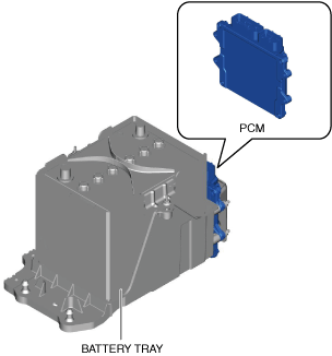
• Installed on the battery tray.
am3zzn00009651
|
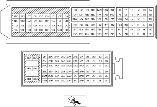
• A 186-pin (two-block) connector has been adopted.
ac5wzw00010964
|
• BARO sensor is integrated.
Operation
• For operation content, refer to the following references:
|
Function |
Page |
|---|---|
|
Main relay control
|
|
|
Drive-by-wire control
|
|
|
Hydraulic variable valve timing control
|
|
|
Electric variable valve timing control
|
|
|
Fuel injection control
|
|
|
Fuel pump control
|
|
|
High pressure fuel pump control
|
|
|
Electronic spark advance control
|
|
|
Purge control
|
|
|
A/F sensor heater control
|
|
|
HO2S heater control
|
|
|
A/C cut-off control
|
|
|
Electrical fan control
|
|
|
Starter cut-off control
|
|
|
Generator control
|
|
|
Engine oil variable control
|
|
|
Water flow control
|