HYDRAULIC VARIABLE VALVE TIMING CONTROL [SKYACTIV-G (WITHOUT CYLINDER DEACTIVATION (US))]
HYDRAULIC VARIABLE VALVE TIMING CONTROL [SKYACTIV-G (WITHOUT CYLINDER DEACTIVATION (US))]
SM2565344
id0140u0318000
Outline
• Changes the exhaust valve timing according to engine operation conditions to improve engine output, fuel economy, and emission performance.
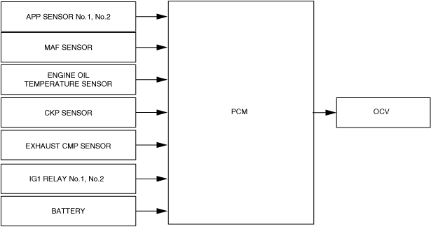
• Based on each input signal, the PCM determines the optimum exhaust valve timing according to the engine operation conditions. The PCM drives the OCV, and switches the oil passages of the hydraulic variable valve timing actuator to control the exhaust valve timing at optimum.
• Based on the coordination with the electric variable valve timing control and by increasing the amount of overlap during high engine loads, nitrogen oxide (NOx) occurring largely at high temperatures is reduced by re-circulating exhaust gas into the combustion chamber, which reduces combustion temperature.
Block Diagram
am3zzn00008279
|
Operation
Exhaust valve timing determination
-
• The PCM controls current to the OCV to obtain optimum exhaust valve timing according to the engine operation conditions (target exhaust valve timing).• In addition to controlling the OCV drive current value to obtain the target exhaust valve timing, the PCM compares the value with the actual exhaust valve timing to correct the OCV drive current value if necessary.
-
Target exhaust valve timing
-
• The target exhaust valve timing is determined by the engine speed and the charging efficiency.
-
Actual exhaust valve timing
-
• The actual exhaust valve timing is calculated by subtracting the cam maximum advance learning value from the value (retard amount) detected by the exhaust camshaft position sensor and crankshaft position sensor.
-
Cam maximum advance learning value
-
• Though the exhaust camshaft valve timing (including maximum advance position) is detected based on the difference in the rise between the exhaust camshaft position sensor and the crankshaft position sensor signals, variation in signals from the assembly of each sensor occurs. As a result, the PCM stores the difference in the rise of the exhaust camshaft position sensor and crankshaft position signals to prevent detection of variations in the exhaust valve timing.
OCV drive current determination
-
• The PCM divides the oil control valve OCV drive range into three modes according to engine operation conditions. The OCV drive current is determined based on the target current calculated in each mode.
Range mode table
|
Mode name |
Control description |
|---|---|
|
Feedback mode
|
• The feedback mode constantly monitors whether the target exhaust valve timing is the determined value according to the engine operation conditions and controls the OCV drive current based on the results.
|
|
Cleaning mode
|
• Cleaning mode is to remove foreign material in the OCV oil passages.
|
|
Cam advance mode
|
• If the cam advance is appropriate according to engine operation conditions such as while in torque down execution during idling, the cam advance mode advances the exhaust valve timing and stabilizes the engine speed.
|