DETERMINING SHORT TO GROUND LOCATION (CAN-BUS No.5) [(US)]
DETERMINING SHORT TO GROUND LOCATION (CAN-BUS No.5) [(US)]
SM2566460
id1002x1003400
-
Caution
-
• Perform the following malfunction diagnosis only when it is diagnosed with a short to ground by CONTROLLER AREA NETWORK (CAN) MALFUNCTION DIAGNOSIS FLOW. (See CONTROLLER AREA NETWORK (CAN) MALFUNCTION DIAGNOSIS FLOW [(US)].)
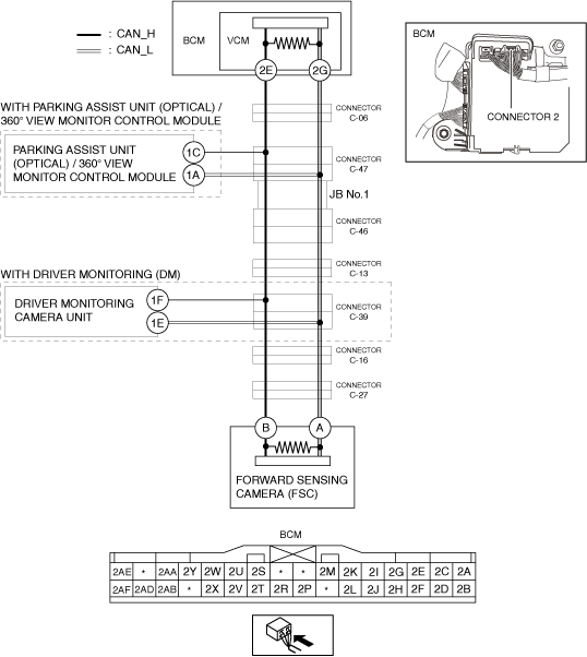
System Wiring Diagram
am3zzw00027508
|
Determination Procedure
-
Caution
-
• When disconnecting the connector, verify that there is no looseness, damage, deformation, corrosion, or poor connection of the connector terminals.• When inspecting the connector, touch it with a paper clip or similar thin pin without directly inserting a tester probe into the terminal.
|
Step |
Inspection |
Action |
|
|---|---|---|---|
|
1
|
INSPECT CAN LINE IN BODY CONTROL MODULE (BCM) FOR SHORT TO GROUND
• Switch the ignition off.
• Disconnect the negative battery cable. (See NEGATIVE BATTERY TERMINAL DISCONNECTION/CONNECTION [(US)])
• Disconnect the connector 2 which has body control module (BCM) terminals 2E and 2G.
• Inspect for continuity at the following terminals:
• Is there continuity?
|
Yes
|
Go to the next step.
|
|
No
|
Replace the body control module (BCM) because there is a short to ground in the body control module (BCM).
|
||
|
2
|
INSPECT FOR SHORT TO GROUND BETWEEN BODY CONTROL MODULE (BCM) AND CONNECTOR C-06
• Disconnect the connector C-06.
• Connect the connector 2 which has body control module (BCM) terminals 2E and 2G.
• Inspect for continuity at the following terminals:
• Is there continuity?
|
Yes
|
Repair or replace the wiring harness between the body control module (BCM) and connector C-06 because the wiring harness is shorted to ground.
|
|
No
|
Go to the next step.
|
||
|
3
|
INSPECT FOR SHORT TO GROUND BETWEEN CONNECTOR C-47 AND CONNECTOR C-06
• Disconnect the connector C-47.
• Connect the connector C-06.
• Inspect for continuity at the following terminals:
• Is there continuity?
|
Yes
|
Repair or replace the wiring harness between the connector C-47 and connector C-06 because the wiring harness is shorted to ground.
|
|
No
|
Go to the next step.
|
||
|
4
|
INSPECT FOR SHORT TO GROUND BETWEEN PARKING ASSIST UNIT (OPTICAL) / 360° VIEW MONITORING CAMERA UNIT AND CONNECTOR C-47
• Inspect for continuity at the following terminals:
• Is there continuity?
|
Yes
|
Go to the next step.
|
|
No
|
Go to Step 6.
|
||
|
5
|
INSPECT CAN LINE IN PARKING ASSIST UNIT (OPTICAL) / 360° VIEW MONITORING CAMERA UNIT FOR SHORT TO GROUND
• Disconnect the parking assist unit (optical) / 360° view monitoring camera unit connector.
• Inspect for continuity at the following terminals:
• Is there continuity?
|
Yes
|
Repair or replace the wiring harness between the parking assist unit (optical) / 360° view monitoring camera unit and connector C-47 because the wiring harness is shorted to ground.
|
|
No
|
Replace the parking assist unit (optical) / 360° view monitoring camera unit because there is a short to ground in the parking assist unit (optical) / 360° view monitoring camera unit.
|
||
|
6
|
INSPECT CAN LINE IN JB No.1 FOR SHORT TO GROUND
• Disconnect the connector C-46.
• Connect the connector C-47.
• Inspect for continuity at the following terminals:
• Is there continuity?
|
Yes
|
Replace the JB No.1 because there is a short to ground in the JB No.1.
|
|
No
|
Go to the next step.
|
||
|
7
|
INSPECT FOR SHORT TO GROUND BETWEEN CONNECTOR C-13 AND CONNECTOR C-46
• Disconnect the connector C-13.
• Connect the connector C-46.
• Inspect for continuity at the following terminals:
• Is there continuity?
|
Yes
|
Repair or replace the wiring harness between the connector C-13 and connector C-46 because the wiring harness is shorted to ground.
|
|
No
|
Go to the next step.
|
||
|
8
|
INSPECT FOR SHORT TO GROUND BETWEEN CONNECTOR C-39 AND CONNECTOR C-13
• Disconnect the connector C-39.
• Connect the connector C-13.
• Inspect for continuity at the following terminals:
• Is there continuity?
|
Yes
|
Repair or replace the wiring harness between the connector C-39 and connector C-13 because the wiring harness is shorted to ground.
|
|
No
|
Go to the next step.
|
||
|
9
|
INSPECT FOR SHORT TO GROUND BETWEEN DRIVER MONITORING CAMERA UNIT AND CONNECTOR C-39
• Inspect for continuity at the following terminals:
• Is there continuity?
|
Yes
|
Go to the next step.
|
|
No
|
Go to Step 11.
|
||
|
10
|
INSPECT CAN LINE IN DRIVER MONITORING CAMERA UNIT FOR SHORT TO GROUND
• Disconnect the driver monitoring camera unit connector.
• Inspect for continuity at the following terminals:
• Is there continuity?
|
Yes
|
Repair or replace the wiring harness between the driver monitoring camera unit and connector C-39 because the wiring harness is shorted to ground.
|
|
No
|
Replace the driver monitoring camera unit because there is a short to ground in the driver monitoring camera unit.
|
||
|
11
|
INSPECT FOR SHORT TO GROUND BETWEEN CONNECTOR C-16 AND CONNECTOR C-39
• Disconnect the connector C-16.
• Connect the connector C-39.
• Inspect for continuity at the following terminals:
• Is there continuity?
|
Yes
|
Repair or replace the wiring harness between the connector C-16 and connector C-39 because the wiring harness is shorted to ground.
|
|
No
|
Go to the next step.
|
||
|
12
|
INSPECT FOR SHORT TO GROUND BETWEEN CONNECTOR C-27 AND CONNECTOR C-16
• Disconnect the connector C-27.
• Connect the connector C-16.
• Inspect for continuity at the following terminals:
• Is there continuity?
|
Yes
|
Repair or replace the wiring harness between the connector C-27 and connector C-16 because the wiring harness is shorted to ground.
|
|
No
|
Go to the next step.
|
||
|
13
|
INSPECT CAN LINE IN FORWARD SENSING CAMERA (FSC) FOR SHORT TO GROUND
• Disconnect the forward sensing camera (FSC) connector.
• Inspect for continuity at the following terminals:
• Is there continuity?
|
Yes
|
Repair or replace the wiring harness between the forward sensing camera (FSC) and connector C-27 because the wiring harness is shorted to ground.
|
|
No
|
Replace the forward sensing camera (FSC) because there is a short to ground in the forward sensing camera (FSC).
|
||